Appendix B – Pinouts
B-3
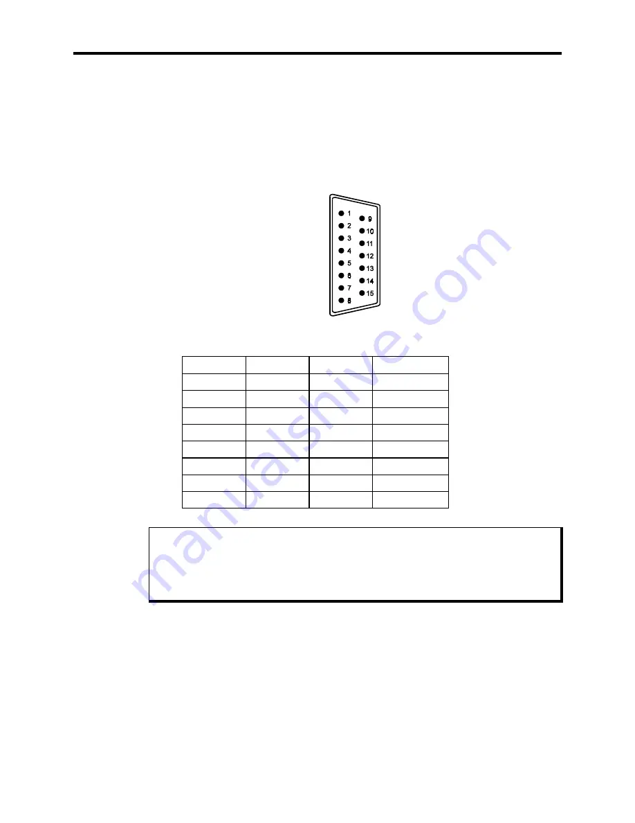
Host/LED Port
The monitor module may be connected to the computer module using a 15-pin cable
between the Host/LED connectors on both modules. This cable carries the keyboard sig-
nals to the computer module from the monitor module’s integrated keypads and any key-
board that is connected to the monitor module’s keyboard ports. This cable also carries
the signals used to light the system status LEDs on the front panel of the monitor mod-
ule. This DB-15M (male) connector is mounted on the rear panel of the monitor module.
Figure Appendix B -3. Host/LED Port Pinout Diagram
Table Appendix B -3. Host/LED Port Connector Pinout (Monitor Module)
Pin
Signal
Pin
Signal
1
+5 VDC
9
MAINT LED
2
+5 VDC
10
CLK
3
+5 VDC
11
FAULT LED
4
+5 VDC
12
COM LED
5
GND
13
DISK LED
6
GND
14
N/C
7
GND
15
DATA
8
GND
Note
When connecting the monitor module to the computer module, use
either
the supplied
Host/LED cable
or
a cable between the monitor module’s keyboard Out port and the
computer module’s Keyboard port (not included),
but not both
. Using both cables will
cause the keyboard to operate improperly.


