


How to customize the MAX 200
203
How to change the copy features (continued)
Folder setup
Note: If your system is set up with a folder, do not put A or A4 size
media into the tray 5, short edge feed. Refer to your user guide for
detailed information.
Introduction
The MAX 200
folder setup
feature
, sets up the MAX 200 fold
parameters for three folds assigned to P1, P2 and P3. For detailed
information on the type of folds refer to the section,
Folder
terminology
.
Once the MAX 200 program fold parameters are setup, you can
program the fold default for copy mode and plot mode. To go directly
to the folder setup procedure go to page 205.
•
To setup the fold default for copy mode, refer to page 159.
•
To setup the fold default for plot mode, refer to page 187.
To go directly to the folder setup procedure go to page 205.
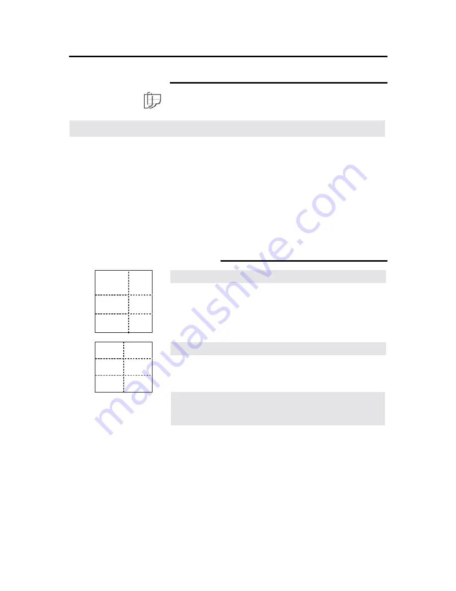
Folder terminology
Fan fold
Creates packages folded to A-size, panels do not need to be equal
size. Binding margins can be added to fan fold.
Cross fold
Creates packages folded to A-size, panels are not equal in size. No
binding margin can be added.
Other packet sizes available
Punch, tab, reinforce
Smaller, Bigger
Packet size
Off
Smaller
185 x 297 mm
Off
Standard
190 x 297 mm
Off
Bigger
198 x 297 mm
On
Smaller
198 x 297
2
mm
On
Standard
198 x 297 mm or
210 x 297
3
mm
On
Bigger
210 x 297 mm
2
Tabs sticks out 12 mm from paper, the full packet is 198+ 12=
210 mm wide.
3
The folder can be set to 198 or 210 as the standard size for tabs to
be added to.


