background image

4 | Electric motors for explosive atmospheres

For motors with degree of protection IP56, IP65 or IP66, the drain plugs must remain at closed position, being opened only during the motor 

maintenance procedures.

"Automatic" rubber drain plugs are designed for one use only and cannot be reused. If any drain plug is removed for any purpose, it must always 

be replaced by a new one.

The drain system of motors with Oil Mist lubrication system must be connected to a specific collection system.

The drain plugs of explosion proof motors cannot be removed during installation and maintenance procedures.

When provided with a breather-drain to certificate IECEx CSA 12.0005U, the motors are limited to Groups IIB, IIC and IIIC, an ambient 

temperature of -55 °C to + 40 °C, temperature classification T5 to T2, and have a degree of protection of IP6X (for group IIIC).

Do not block the motor ventilation openings. Ensure a minimum clearance of ¼ of the diameter of the air intake of the fan cover from the walls. 

The air used for cooling the motor must be at ambient temperature, limited to the temperature range indicated on the motor nameplate (when not 

indicated, -20 °C to +40 °C must be considered).

Motors installed outdoors or in the vertical position require the use of additional shelter to protect them from water; for instance, use of a drip cover.

To prevent accidents, ensure that the grounding connection has been performed according to the applicable standards and that the shaft key 

has been well-fixed fastened before the motor is started. 

Connect the motor properly to the power supply by means of safe and permanent contacts, always considering the data informed on the 

nameplate, such as rated voltage, wiring diagram, etc.

When motors are supplied with flying leads, they must be suitably connected to an appropriate terminal box required for the use condition (type 

of protection).

When using terminals, all wires that form the stranded cable must be fastened inside the sleeve. The insulation of the accessories cables must 

be kept up to 1 mm from the connector connection point.

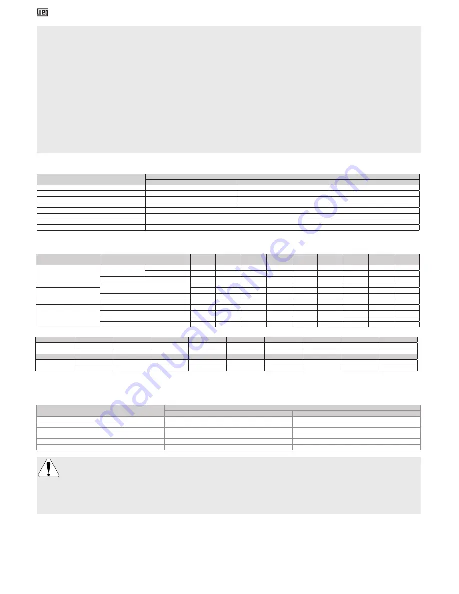
When provided with terminal blocks marked with “W-A12”, “W-B12 (160V)” or “W-B12 (500V)”, the following characteristics must be respected:

Table 1

 - Terminal block type designation

For power cables and grounding system connections and terminal box assembly, the tightening torques indicated on Tables 2 and 3 must be respected.

Table 2

 - Tightening torques for fixing elements [Nm]

Table 3

 - Tightening torques for cable glands and plugs [Nm]

For power cables, switching and protection devices dimensioning, consider the rated motor current, the service factor, and the cable length, among 

others. For motors without terminal block, insulate the motor terminal cables by using insulating materials that are compatible with the insulation class 

informed on the nameplate. The minimum insulation distance between the non-insulated live parts themselves and between live parts and the grounding 

must respect the Table 4.

Table 4 - 

Minimum insulation distance (mm)

Voltage

Type of protection of the enclosure

Ex e / Ex de

Ex n/ Ex d/ Ex t

U ≤ 440 V

6

4

440 < U ≤ 690 V

10

5.5

690 < U ≤ 1000 V

14

8

1000 < U ≤ 6900 V

60

45

6900 < U ≤ 11000 V

100

70

11000 <U ≤ 16500 V

-

105

Take the required measures in order to ensure the type of protection, the EPL and the degree of protection indicated on the motor 

nameplate:

- not-used cable inlet holes in the terminal boxes must be properly closed with certified plugs;

- components supplied loose (for example, terminal boxes mounted separately) must be properly closed and sealed;

The cable entries used must be fitted with components (such as, cable glands and conduits) that meet the applicable standards and 

regulations for each country. For “Ex d” motors, the conduit entries are permitted only for electrical equipment of group II.
The fixing elements mounted in the threaded through holes in the motor enclosure (for example, the flange) must be properly sealed, with 

the products listed in item 5, to ensure the degree of protection indicated on the motor nameplate.


The motor must be installed with overload protection devices. These protection devices can be integrated to the motor (such as thermistors in the windings) 

or external protection devices, where the motor load is monitored by the nominal current. For three-phase motors, it is recommended to install a phase failure 

protection device. Motors driven by variable frequency drives must have their winding thermal protections connected. For other starting methods, the use of the 

thermal protections is optional. For “Ex n”, “Ex ec”, “Ex d/Ex db”, “Ex de/Ex db eb”, “Ex tb” and “Ex tc” motors: all thermal protections (RTDs, bimetal thermal 

protectors and thermistors for stator protection) used in the motor protection circuit can be connected via a standard industrial controller located in a safe area.   

For “Ex eb” motors: all thermal protections (RTDs, bimetal thermal protectors and thermistors for stator protection) used in the motor protection circuit must be 

separately protected by the use of an intrinsic safety supply that ensures the minimum EPL Gb level of protection. 

Ensure the correct operation of the accessories (brake, encoder, thermal protection, forced ventilation, etc.) installed on the motor before it is started.The temperature 

limits for alarm and tripping of the thermal protection can be defined according to the application, however they may not exceed the values shown in Table 5.

Thread

Material

M16

M20

M25

M32

M40

M50

M63

M80

Metric

Plastic

3 to 5

3 to 5

6 to 8

6 to 8

6 to 8

6 to 8

6 to 8

6 to 8

Metallic

40 to 50

40 to 50

55 to 70

65 to 80

80 to 100

100 to 120

115 to 140

160 to 190

Thread

Material

NPT  1/2"

NPT  3/4"

NPT  1"

NPT  1 1/2"

NPT  2"

NPT  2 1/2"

NPT  3"

NPT  4"

NPT

Plastic

-

5 to 6

6 to 8

6 to 8

6 to 8

6 to 8

6 to 8

6 to 8

Metallic

40 to 50

40 to 50

55 to 70

65 to 80

100 to 120

115 to 140

150 to 175

200 to 240

Type of protection 

of enclosure

Component

M4

M5

M6

M8

M10

M12

M14

M16

M20

Ex d 

Ex de

Terminal Box Cover

Class 8.8/12.9

-

3.5 to 5

6 to 12

14 to 30

28 to 60

45 to 105

75 to 110

115 to 170 230 to 330

Class A2-70 / A4-70

-

3.5 to 5

6 to 8.5

14 to 19

28 to 40

45 to 60

75 to 100 115 to 170 225 to 290

Grounding

1.5 to 3

3 to 5

5 to 10

10 to 18

28 to 40

45 to 70

-

115 to 170

-

Ex d

Terminal block

1 to 1.5

2 to 4

4 to 6.5

6.5 to 9

10 to 18

15.5 to 30

-

30 to 50

50 to 75

Ex de

1 to 1.5

2 to 4

4 to 6.5

6.5 to 9

5 to 9

10 to 15

-

20 to 30

-

Locking bolt for connection clamp

-

3 to 7

4 to 8

7 to 11

-

-

-

-

-

Locking bolt for power cables

-

-

-

2 to 6

6 to 10

-

-

-

-

Ex n 

Ex t 

Ex e

Terminal box cover

-

3 to 5

4 to 8

8 to 15

18 to 30

25 to 40

30 to 45

35 to 50

-

Grounding

1.5 to 3

3 to 5

5 to 10

10 to 18

28 to 40

45 to 70

-

115 to 170

-

Terminal block

1 to 1.5

2 to 4

4 to 6.5

6.5 to 9

10 to 18

15.5 to 30

-

30 to 50

50 to 75

Terminal block fixing bolts

-

3 to 5

5 to 10

10 to 18

28 to 40

45 to 70

75 to 110

115 to 170

-

Characteristic

Terminal block type designation

W-A12

W-B12 (160 V)

W-B12 (500 V)

Voltage

Up to 160 V

Up to 160 V

Up to 500 V

Current

Max. 15 A

Max. 15 A

Max. 20 A

Conductor cross-section

0,3 to 2,5 mm²

0,3 to 4 mm²

0,3 to 4 mm²

Number of cables per terminal connection

2x1 mm²

2x1,5 mm²

2x1,5 mm²

Connection torque

0,5 to 0,7 Nm

Service temperature

-20 °C to + 80 °C

ATEX marking/certificate

II 2G Ex eb IIC Gb / I M2 Ex eb I Mb / PTB 06 ATEX 1078 U

IECEx marking/certificate

Ex eb IIC Gb / Ex eb I Mb / IECEx PTB 17.0014U

Summary of Contents for W21Xd

Page 1: ...ctricos para atm sferas explosivas Manual de instalaci n operaci n y mantenimiento de motores el ctricos Elektrische motoren voor explosiegevaarlijke omgevingen Handleiding voor installatie bediening...

Page 2: ...EN 60079 15 2010 EN 60079 31 2014 EN 60204 1 2006 A1 2009 AC 2010 and EN 60204 11 2000 AC 2010 A comparison of the current version of the EN 60079 0 2012 A11 2013 EN 60079 1 2014 EN 60079 15 2010 and...

Page 3: ...against dust vibrations gases and corrosive agents with relative humidity not over 60 In order to prevent water condensation within the motor during the storage period it is recommended to keep the sp...

Page 4: ...ust be fitted with components such as cable glands and conduits that meet the applicable standards and regulations for each country For Ex d motors the conduit entries are permitted only for electrica...

Page 5: ...y period must be performed by a WEG authorized service center for Explosive Atmospheres only For motors with permanent magnet rotor lines W22 Quattro and W22 Magnet the motor assembly and disassembly...

Page 6: ...es extend the equipment warranty period WEG s Civil Liability is limited to the supplied product WEG will not be liable for indirect or consequential damages such as losses of profit and revenue losse...

Page 7: ...ala o do motor A n o ser que haja especifica o ao contr rio no pedido de compra os motores WEG s o balanceados dinamicamente com meia chaveta e em vazio desacoplados Os elementos de transmiss o como p...

Page 8: ...segura que garanta o m nimo n vel de prote o EPL Gb Verifique o correto funcionamento dos acess rios freio encoder prote o t rmica ventila o for ada etc instalados no motor antes de coloc lo em opera...

Page 9: ...plos o e suas respectivas tampas a folga entre as mesmas n o deve exceder os valores indicados na Tabela 6 Tabela 6 Folga m xima entre tampa e caixa de liga o para motores prova de explos o Linha de p...

Page 10: ...clasificaci n del rea de instalaci n y de las caracter sticas del ambiente es de responsabilidad del usuario Los motores el ctricos tienen circuitos bajo tensi n y componentes giratorios que pueden ca...

Page 11: ...las normas vigentes y que la conexi n est bien apretada Conecte el motor correctamente a la red el ctrica a trav s de contactos seguros y permanentes siguiendo siempre los datos mostrados en la placa...

Page 12: ...conexi n Bobinado Ex d Ex d 130 150 Ex n Ex n 130 155 Ex t Ex t 120 140 Ex e Ex e 110 Ex n Ex t Ex n 140 155 Ex t 140 Ex d Ex t Ex d 140 150 Ex t 140 Class I Div 1 Class I Div 1 130 150 Class I Div 2...

Page 13: ...ccione peri dicamente el funcionamiento del motor seg n su aplicaci n asegur ndose de que el aire fluya libremente Inspeccione los sellos los tornillos de fijaci n los cojinetes los niveles de vibraci...

Page 14: ...enen Angaben m ssen denen der Rechnung der Betriebsumgebungsbedingungen in welcher der Motor eingesetzt wird und der Z ndschutzart dem Ger teschutzniveau EPL entsprechen Wird der Motor nicht sofort in...

Page 15: ...fen geliefert d rfen diese Motoren nur in den Gruppen IIB IIC und IIIC f r Umgebungstemperaturen von 55 C bis 40 C und in der Temperaturklassen T5 bis T2 eingesetzt werden F r Gruppen IIIC muss die Sc...

Page 16: ...der blockiertem Motor mit Verz gerung in Abh ngigkeit der Motorspannung ansprechen und die externen Versorgungskabel indirekt berwachen Die auf dem Typenschild angegebene Zeit tE darf nicht berschritt...

Page 17: ...er Transport Lagerung Handhabung Installation Betrieb und Wartung der Elektromotoren steht Ihnen die Webseite www weg net zur Verf gung Auch f r Motoren mit Sonderanwendungen oder erschwerten Betriebs...

Page 18: ...teur n est pas install tout de suite le stocker dans un endroit sec exempt de poussi re de vibrations de gaz et d agents abrasifs et avec une humidit relative de l air inf rieure 60 Afin d viter la co...

Page 19: ...5 6 6 8 6 8 6 8 6 8 6 8 6 8 M tallique 40 50 40 50 55 70 65 80 100 120 115 140 150 175 200 240 Le moteur doit toujours tre positionn de sorte que le trou de drainage se trouve la position la plus bas...

Page 20: ...n est pas recommand e Les moteurs quip s de roulement rouleaux ont besoin d une charge radiale minimum pour un fonctionnement satisfaisant Lors de l arr t d un moteur quip de syst mes de lubrification...

Page 21: ...iode de garantie diff rente est d finie dans la proposition technico commerciale d une vente particuli re elle remplacera les d lais dict s ci dessus Les d lais de garantie tablis ci dessus sont ind p...

Page 22: ...for explosive atmospheres 22 1 WEG g g g g Ex e g Ex n g Ex d Ex de g Ex t g Class I Division 1 g Class I Division 2 g Class II Division 1 g Class II Division 2 50034162 www weg net WEG EPL X 2 WEG 6...

Page 23: ...5 30 30 50 50 75 Ex de 1 1 5 2 4 4 6 5 6 5 9 5 9 10 15 20 30 3 7 4 8 7 11 2 6 6 10 Ex n Ex t Ex e 3 5 4 8 8 15 18 30 25 40 30 45 35 50 1 5 3 3 5 5 10 10 18 28 40 45 70 115 170 1 1 5 2 4 4 6 5 6 5 9 1...

Page 24: ...5 5 C Ex d Ex d 130 150 Ex n Ex n 130 155 Ex t Ex t 120 140 Ex e Ex e 110 Ex n Ex t Ex n 140 155 Ex t 140 Ex d Ex t Ex d 140 150 Ex t 140 Class I Div 1 Class I Div 1 130 150 Class I Div 2 Class I Div...

Page 25: ...ote DC 33 Dow Corning 55 C 80 C Loctite 5923 Henkel 6 6 W21Xd 90 355 NEMA 143 586 7 0 05 W22Xd 71 80 0 15 12 5 90 355 NEMA 143 586 8 0 075 6 0 15 19 2 12 9 A2 70 A4 70 I III 5 6 7 W22Xd W22Xt W22Xn 12...

Page 26: ...chermingtype en het EPL van de motor Indien de motor niet onmiddellijk wordt ge nstalleerd raden wij u aan de motor te bewaren in een schone en droge plaats vrij van stof trillingen en agressieve chem...

Page 27: ...nder anderen de nominale motorstroom de bedrijfsfactor en de lengte van de kabels Voor motoren zonder klemmenbord isoleer de eindkabels van de motor met behulp van isolatiematerialen in overeenstemmin...

Page 28: ...atie over het gebruik van de frequentieomvormer moet men verplicht de instructies volgen van de handleiding van de motor op de site www weg net en van de handleiding van de frequentieomvormer 4 BEDIEN...

Page 29: ...Motors Business Unit WEG biedt garantie tegen defecten in het geleverde werk en materiaal van zijn producten De garantie is geldig gedurende 18 maanden gerekend vanaf de factuurdatum van de fabriek of...

Page 30: ...cui il motore verr installato al tipo di protezione e al tipo di EPL del motore Nel caso in cui il motore non dovesse venir installato immediatamente si raccomanda di conservarlo in luogo pulito e asc...

Page 31: ...ando viene utilizzato il terminale tutti i fili che formano il cavo multifilo devono essere fissati all interno della guaina L isolamento dei cavi degli accessori dev essere tenuto ad una distanza mas...

Page 32: ...ire scollegare il motore dalla rete elettrica e verificare la causa per cui intervenuta la protezione termica Per ulteriori informazioni circa l uso del convertitore di frequenza obbligatorio seguire...

Page 33: ...TERMINI DI GARANZIA WEG Equipamentos El tricos S A Divisione motori WEG offre una garanzia che copre i difetti di mano d opera e materiali per i propri prodotti per un periodo di 18 mesi a decorrere...

Page 34: ...g Ex e g n Ex n g Ex d Ex de g Ex t g Class I Div 1 g Class I Div 2 g Class II Div 1 g Class II Div 2 50034162 www weg net WEG www weg net EPL X 2 WEG 60 5 ISOVG68 3 WEG IP55 IP56 IP65 IP66 20 C 40 C...

Page 35: ...1 2 NPT 2 NPT 2 1 2 NPT 3 NPT 4 NPT 5 6 6 8 6 8 6 8 6 8 6 8 6 8 40 50 40 50 55 70 65 80 100 120 115 140 150 175 200 240 W A12 W B12 160V W B12 500V 1 1 2 Nm 3 Nm 3 4 mm EPL IP Ex d II 5 Ex n Ex ec Ex...

Page 36: ...2 18 WEG WEG WEG WEG WEG WEG WEP WEG WEG WEG 4 WEG 5 WEG W22 Quattro W22 Magnet WEG 60 IEC 71 200 NEMA 143 5 324 6 150 IEC 225 355 NEMA 364 5 586 7 W50 HGF IP55 Lumomoly PT 4 Lumobras 20 C 80 C Molyko...

Page 37: ...Ex nA IIC T3 Gc IECEx BAS 10 0104X 315 450 W50X Ex nA IIC T3 Gc IECEx BAS 10 0104X 63 355 W21 Ex t Ex tc IIIB T125 C Dc IECEx BAS 10 0045X 63 355 W21 Ex t Ex tb IIIC T125 C Db IECEx BAS 10 0099X W22X...

Page 38: ...I Mb X 1Ex d e IIA IIB IIC T4 T6 Gb X Ex d e I Mc X 225 280 1Ex d IIB T2 T6 Gb X PB Ex d I Mb X 1Ex d e IIB T2 T6 Gb X Ex d e I Mc X 55 C Ta 80 C TC RU C BR AA87 B 00697 225 355 1Ex d IIC T2 T6 Gb X...

Page 39: ...eefa14ATEX0208X II 2G Ex de I IIB IIC T4 Gb 20 C Ta 80 C 280 355 II 2G Ex db IIB T4 Gb 20 C Ta 80 C Baseefa15ATEX0152X II 2G Ex db eb IIB T4 Gb 20 C Ta 80 C I M2 Ex db I T4 Mb II 2G Ex db IIB or IIC T...

Page 40: ...RRARI S R L Via Cremona 25 26015 Soresina CR Cremona Phone 39 374 340 404 www ferrarisrl it STIAVELLI IRIO S P A Via Pantano Blocco 16 Capalle 50010 Campi Bisenzio FI Phone 39 55 898 448 www stiavelli...

Reviews: