17
November 2008
Part No. 920559 Rev H
2.10 Balance Vapor Recovery System Installation Requirements,
continued
6. If back pressure readings are very low (less than .02 @ 20 CFH; 0.18 @ 60 CFH; 0.4 @ 100 CFH):
1. Check test fixture for tight seal at nozzle entry point.
2. Check bellows and face seal for tears.
3. Check vapor piping for leaks.
7. If back pressure readings are high:
1. Check hoses and nozzle bellows are completely drained.
2. Check dry break is open. (If only allowed to have one dry break open during the test, try all.)
3. Check vapor pod.
4. Check vapor impact valve to be open.
5. Check piping under dispenser. Should be a minimum of 1 inch diameter piping and fitting.
6. Check dispenser back pressure, disconnected from the underground and compare to dispenser base line
data.
7. Check hanging hardware separate from dispenser and compare to balance hardware matrix base line
data.
8. Check outlets, hose, and underground, for suspect blockage problems due to fitting bottomed out or
casting flashing. Flashing is aluminum edges left over when the casting was made. This should be your
last resort to diagnosing high back pressure readings since piping will have to be removed to look
inside the casting for flashing. A large amount of flashing would be required to affect readings.
2.10.3 Nozzles Approved for Balance System
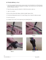
The Ovation nozzle boot hook can be adjusted to accommodate different nozzles. Table 2-1 shows the nozzles
approved for use with a balance system and the hook position for each nozzle. Position 1 is the standard posi-
tion. The hook is in position 1 in the accompanying photo. To change positions, remove the (4) screws shown,
slide the hook down to the new position, and reinstall the (4) screws to secure the hook to the boot.
Table 2-1 Nozzle and Nozzle Hook Position
NOZZLE
HOOK POSITION
Emco Wheaton A4005
3
Emco Wheaton A4015
1
OPW 11VF47
4
Husky V Model 5010 and 5020
3
Husky V(short) Model 5110 and 5210
1
1/4-20
Screws (4)
Summary of Contents for Ovation
Page 1: ...INSTALLATION Ovation Dispensers OPERATION...
Page 3: ...November 2008 Part No 920559 Rev H Ovation Series Dispensers Installation Operation...
Page 4: ...November 2008 Part No 920559 Rev H...
Page 54: ...48 Part No 920559 Rev H November 2008...
Page 66: ...60 Part No 920559 Rev H November 2008...
Page 67: ...61 November 2008 Part No 920559 Rev H DISTANCE BETWEEN EYE BOLTS 33 1...
Page 68: ...62 Part No 920559 Rev H November 2008 INSTALLATION INSTRUCTION page 1 of 2 OVATION MODEL R13...
Page 69: ...63 November 2008 Part No 920559 Rev H INSTALLATION INSTRUCTION page 2 of 2 OVATION MODEL R13...
Page 70: ...64 Part No 920559 Rev H November 2008 INSTALLATION INSTRUCTION page 1 of 2 OVATION MODEL B23...
Page 71: ...65 November 2008 Part No 920559 Rev H INSTALLATION INSTRUCTION page 2 of 2 OVATION MODEL B23...
Page 74: ...68 Part No 920559 Rev H November 2008 INSTALLATION INSTRUCTION page 1 of 2 OVATION MODEL R11...
Page 75: ...69 November 2008 Part No 920559 Rev H INSTALLATION INSTRUCTION page 2 of 2 OVATION MODEL R11...
Page 76: ...70 November 2008 Part No 920559 Rev H...
Page 77: ...71 November 2008 Part No 920559 Rev H 2 7151 C TYPICAL SITE WIRING...
Page 78: ...72 Part No 920559 Rev H November 2008...
Page 80: ...74 Part No 920559 Rev H November 2008...
Page 81: ...75 November 2008 Part No 920559 Rev H APPENDIX D SITE INTERCONNECTION DIAGRAMS...
Page 82: ...76 Part No 920559 Rev H November 2008 Figure D 1 Backroom Installation Wayne Control System...
Page 84: ...78 Part No 920559 Rev H November 2008 Figure D 3 Pump Relay Installation Wiring Diagram...

