27
November 2008
Part No. 920559 Rev H
3.7 Setting the Fueling Point ID
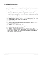
The procedure below is used to set the pump fueling point address. The pump FPID should be input and
saved before control is transferred to the POS system.
Functions
F05
and
F06
are accessed to set the FPID on Side 1 and Side 2, respectively. To set the FPID, the
desired FPID must be input and saved.
Accessing the FPID Function.
1. Press
ENTER
PASS 1
(enter password)
2. Press
ENTER
PASS 2
(enter password)
3. Press
ENTER.
The unit price display will show
F—
(indicating that it needs a function number to pro-
ceed)
4. Press
05
to access
F05
5. Press
ENTER.
The unit price display will show
F05
indicating the function has been accessed and the
volume display will show the current FPID or a “
0
” when no FPID has been assigned to that dispenser
side.
6. Input the desired FPID by using the
UP
and
DOWN
keys on the remote control interface followed by
ENTER
, or by typing the # sign followed by the valve of the FPID followed by
ENTER
.
7. Repeat the procedure for Side 2.
Saving the New FPID
1. Press
ENTER.
The price display will show “–
– – – – –
“, the volume display will be blank and the unit
price display will show the last sub-function accessed.
2. Press
00
(to access F00)
3. Press
ENTER.
The unit price should now display
F00
, the price display will show “–
– – – – –
“and the
volume display will be blank.
4. Press
ENTER
and the volume display will show a
1
.
5. Press
UP
twice to change the value in the volume display from
1
to
3.
6. Press
ENTER
7. The volume display should show a
3
.
8. Press
ENTER.
CHANGE STORED
should appear on the display momentarily. The display should return
to normal in a few seconds. When it does, the unit price displays should show the new prices. If they do
not show the desired unit prices, access the appropriate sub-function to make sure that the unit price data
is correct.
8. Repeat the procedure for Side 2.
Note: For models equipped with IDPOS, see configration in Section 4.
Summary of Contents for Ovation
Page 1: ...INSTALLATION Ovation Dispensers OPERATION...
Page 3: ...November 2008 Part No 920559 Rev H Ovation Series Dispensers Installation Operation...
Page 4: ...November 2008 Part No 920559 Rev H...
Page 54: ...48 Part No 920559 Rev H November 2008...
Page 66: ...60 Part No 920559 Rev H November 2008...
Page 67: ...61 November 2008 Part No 920559 Rev H DISTANCE BETWEEN EYE BOLTS 33 1...
Page 68: ...62 Part No 920559 Rev H November 2008 INSTALLATION INSTRUCTION page 1 of 2 OVATION MODEL R13...
Page 69: ...63 November 2008 Part No 920559 Rev H INSTALLATION INSTRUCTION page 2 of 2 OVATION MODEL R13...
Page 70: ...64 Part No 920559 Rev H November 2008 INSTALLATION INSTRUCTION page 1 of 2 OVATION MODEL B23...
Page 71: ...65 November 2008 Part No 920559 Rev H INSTALLATION INSTRUCTION page 2 of 2 OVATION MODEL B23...
Page 74: ...68 Part No 920559 Rev H November 2008 INSTALLATION INSTRUCTION page 1 of 2 OVATION MODEL R11...
Page 75: ...69 November 2008 Part No 920559 Rev H INSTALLATION INSTRUCTION page 2 of 2 OVATION MODEL R11...
Page 76: ...70 November 2008 Part No 920559 Rev H...
Page 77: ...71 November 2008 Part No 920559 Rev H 2 7151 C TYPICAL SITE WIRING...
Page 78: ...72 Part No 920559 Rev H November 2008...
Page 80: ...74 Part No 920559 Rev H November 2008...
Page 81: ...75 November 2008 Part No 920559 Rev H APPENDIX D SITE INTERCONNECTION DIAGRAMS...
Page 82: ...76 Part No 920559 Rev H November 2008 Figure D 1 Backroom Installation Wayne Control System...
Page 84: ...78 Part No 920559 Rev H November 2008 Figure D 3 Pump Relay Installation Wiring Diagram...

