6
Part No. 920559 Rev H
November 2008
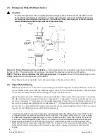
2.3 Emergency Shut-off (Shear) Valves
WARNING
For remote dispensers, a Listed
1
, rigidly anchored emergency shut-off valve must be installed, in accor-
dance with the manufacturer’s instructions, in each supply line at the base of each dispenser. For a typi-
cal emergency valve installation see Figure 2-2. Failure to install the proper emergency shut-off valve will
present a hazardous condition that could result in serious injury.
Note: Wayne does not supply the meter inlet pipe nipple or the union shown above.
2.4 Vapor Return Piping
NFPA 30A Section 4-3-7
2
states that a vapor return pipe inside the dispenser housing shall have a shear sec-
tion or flexible connector so that the liquid emergency shut-off valve will function properly. Wayne’s vapor
connections are secured to the chassis allowing for the use of a shear section.
Wayne dispensers provide 1" NPT pipe connections at the base of the dispenser for vapor return connections.
(See the installation foot print for location in Appendix B.) A minimum 1" riser at each dispenser is con-
nected to a minimum 2" return piping to the underground tank. If more than six (6) fueling points are con-
nected, then underground piping must be a minimum of 3". All lines should be sloped at a minimum of 1/8”
per foot (1/4” per foot preferred) from the dispenser to the tank to avoid liquid traps. Note: There is no vapor
recovery for the Ethanol product on E85 Ovation dispensers.
1. “Listed” means published on a list by a nationally recognized testing laboratory (NRTL) which is responsible for prod-
uct evaluation and is acceptable to the authority having jurisdiction. Underwriters Laboratories, Inc. is one example
of a Nationally Recognized Testing Laboratory. For more information on NRTL’s, see Title 29, Parts 1907 and 1910
of the Code of Federal Regulations, Safety Testing or Certification of Certain Workplace Equipment and Materials.
Figure 2-2 Typical Emergency Valve Installation.
The Emergency valve is designed to close the product line due
to shock or fire. The shear section, shown above, functions if the dispenser is knocked out of position.
NOTE:
The shear valve must always be at the ground plane.
The pedestal shown on the previous page, is con-
sidered an extension of the dispenser, not the island.
2. Reprinted with permission from NFPA 30A-90,
Automotive and Marine Service Stations Codes
, Copyright 1990,
National Fire Protection Association, Quincy MA 02269. This material is not the complete and official position of the
National Fire Protection Association on the referenced subject, which is represented only by the standard in its
entirety.
Summary of Contents for Ovation
Page 1: ...INSTALLATION Ovation Dispensers OPERATION...
Page 3: ...November 2008 Part No 920559 Rev H Ovation Series Dispensers Installation Operation...
Page 4: ...November 2008 Part No 920559 Rev H...
Page 54: ...48 Part No 920559 Rev H November 2008...
Page 66: ...60 Part No 920559 Rev H November 2008...
Page 67: ...61 November 2008 Part No 920559 Rev H DISTANCE BETWEEN EYE BOLTS 33 1...
Page 68: ...62 Part No 920559 Rev H November 2008 INSTALLATION INSTRUCTION page 1 of 2 OVATION MODEL R13...
Page 69: ...63 November 2008 Part No 920559 Rev H INSTALLATION INSTRUCTION page 2 of 2 OVATION MODEL R13...
Page 70: ...64 Part No 920559 Rev H November 2008 INSTALLATION INSTRUCTION page 1 of 2 OVATION MODEL B23...
Page 71: ...65 November 2008 Part No 920559 Rev H INSTALLATION INSTRUCTION page 2 of 2 OVATION MODEL B23...
Page 74: ...68 Part No 920559 Rev H November 2008 INSTALLATION INSTRUCTION page 1 of 2 OVATION MODEL R11...
Page 75: ...69 November 2008 Part No 920559 Rev H INSTALLATION INSTRUCTION page 2 of 2 OVATION MODEL R11...
Page 76: ...70 November 2008 Part No 920559 Rev H...
Page 77: ...71 November 2008 Part No 920559 Rev H 2 7151 C TYPICAL SITE WIRING...
Page 78: ...72 Part No 920559 Rev H November 2008...
Page 80: ...74 Part No 920559 Rev H November 2008...
Page 81: ...75 November 2008 Part No 920559 Rev H APPENDIX D SITE INTERCONNECTION DIAGRAMS...
Page 82: ...76 Part No 920559 Rev H November 2008 Figure D 1 Backroom Installation Wayne Control System...
Page 84: ...78 Part No 920559 Rev H November 2008 Figure D 3 Pump Relay Installation Wiring Diagram...


