20
Part No. 920559 Rev H
November 2008
3.3 Logical Nozzle/Hose Positions
The physical number of hoses on one side of the dispenser is not the same as the number of electronic hose
positions on that side. Unit prices and blend ratios are set in electronic hose position or logical nozzle order.
B23/3, B23/4 and B23/5 model
B
lenders each have
2
hoses per side and
3
inlets, but either 3, 4 or 5 grade
selects/logical nozzles as shown in Figures 3-2 A-C. Logical nozzles are assigned positions 1 through 7,
depending on the dispenser model as shown in Table 3-1.
Three product MGD models have one hose per side and three logical nozzles, which are positions: 1, 2, and
3. For these non-blending models, such as the R13/3, these products are shown as the X, Y, Z products in
Table 3-1.
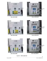
Logical nozzle positions for the Ovation models listed below are also shown in the examples in
Figures 3-2 and 3-3 on the following pages.
Table 3-1
Hose (Logical Nozzle) Positions Defined by V
alues of
N
.
Model number designations are defined as follows:
B23/5 model, B = Blender, 2 = two hoses per side, 3 = three inlets, 5 = five grade selects.
R13/3 model, R = Regular piped non-blender, 1 = one hose per side, 3 = three inlets, 3 = three grade selects.
Ovation Model
# begins with
Dispenser
Description
N=7
N=6
N=5
N=4
N=3
N=2
N=1
B23/5
Two Hose (1+4)
Blender
Lo
Feedstock
Lo-BL
Hi-BL
Hi
Feedstock
Single
Grade
B23/4
Two Hose (1+3)
Blender
Lo
Feedstock
BL
Hi
Feedstock
Single
Grade
B23/3
Two Hose (1+2)
Blender
Lo
Feedstock
Hi
Feedstock
Single
Grade
B12/5
Single Hose 5 Grade
Blender
Lo
Feedstock
Lo-BL
Mid-BL
Hi-BL
Hi
Feedstock
B12/4
Single Hose 4 Grade
Blender
Lo
Feedstock
Lo-BL
Hi-BL
Hi
Feedstock
B12/3
Single Hose 3 Grade
Blender
Lo
Feedstock
BL
Hi
Feedstock
B12/2
Single Hose 2 Grade
Blender
Lo
Feedstock
Hi
Feedstock
R13/3
3 Grade
Non-Blender
Z
Y
X
R22/2
2 Grade
Non-Blender
Y
X
R11/1
1 Grade
Non-Blender
X
Summary of Contents for Ovation
Page 1: ...INSTALLATION Ovation Dispensers OPERATION...
Page 3: ...November 2008 Part No 920559 Rev H Ovation Series Dispensers Installation Operation...
Page 4: ...November 2008 Part No 920559 Rev H...
Page 54: ...48 Part No 920559 Rev H November 2008...
Page 66: ...60 Part No 920559 Rev H November 2008...
Page 67: ...61 November 2008 Part No 920559 Rev H DISTANCE BETWEEN EYE BOLTS 33 1...
Page 68: ...62 Part No 920559 Rev H November 2008 INSTALLATION INSTRUCTION page 1 of 2 OVATION MODEL R13...
Page 69: ...63 November 2008 Part No 920559 Rev H INSTALLATION INSTRUCTION page 2 of 2 OVATION MODEL R13...
Page 70: ...64 Part No 920559 Rev H November 2008 INSTALLATION INSTRUCTION page 1 of 2 OVATION MODEL B23...
Page 71: ...65 November 2008 Part No 920559 Rev H INSTALLATION INSTRUCTION page 2 of 2 OVATION MODEL B23...
Page 74: ...68 Part No 920559 Rev H November 2008 INSTALLATION INSTRUCTION page 1 of 2 OVATION MODEL R11...
Page 75: ...69 November 2008 Part No 920559 Rev H INSTALLATION INSTRUCTION page 2 of 2 OVATION MODEL R11...
Page 76: ...70 November 2008 Part No 920559 Rev H...
Page 77: ...71 November 2008 Part No 920559 Rev H 2 7151 C TYPICAL SITE WIRING...
Page 78: ...72 Part No 920559 Rev H November 2008...
Page 80: ...74 Part No 920559 Rev H November 2008...
Page 81: ...75 November 2008 Part No 920559 Rev H APPENDIX D SITE INTERCONNECTION DIAGRAMS...
Page 82: ...76 Part No 920559 Rev H November 2008 Figure D 1 Backroom Installation Wayne Control System...
Page 84: ...78 Part No 920559 Rev H November 2008 Figure D 3 Pump Relay Installation Wiring Diagram...

