4
Part No. 920559 Rev H
November 2008
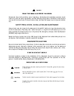
1.3 SAFETY PRECAUTIONS
NFPA 30A states that:
“When maintenance to Class I dispensing devices becomes necessary and such maintenance may
allow the accidental release or ignition of liquid, the following precautions shall be taken before
such maintenance is begun:
•
Only persons knowledgeable in performing the required maintenance shall perform the work.
•
All electrical power to the dispensing device and pump serving the dispenser shall be shut off at
the main electrical disconnect panel.
•
The emergency shut-off valve at the dispenser, if installed, shall be closed.
•
All vehicle traffic and unauthorized persons shall be prevented from coming within 20 ft.(6 m)
of the dispensing device.
1
”
WARNING
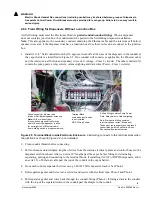
Electric shock hazard! More than one disconnect switch may be required to de-energize the
dispenser for maintenance and servicing. Use a voltmeter to make sure ALL circuits in the
dispenser are de-energized. Failure to do so may result in serious injury.
Lockout/Tagout requirements of the U. S. Dept. of Labor, Occupational Safety and Health Adminis-
tration (OSHA) may also apply. Refer to Title 29, Part 1910 of the Code of Federal Regulations
(29CFR1910),
Control of Hazardous Energy Source (Lockout/Tagout)
.
NOTE:
To prevent damage to components located in the hydraulic cabinet, dispenser doors should be
in place during rainy and/or icy weather conditions. Also, check the nozzle boot flipper for
freedom of movement. If ice has formed on the flipper, it should be cleared to prevent
unnecessary damage.
1. Reprinted with permission from NFPA 30A-90,
Automotive and Marine Service Station Codes
, Copyright
©1990, National Fire Protection Association, Quincy MA 02269. This reprinted material is not the complete
and official position of the National Fire Protection Association on the referenced subject, which is repre-
sented only by the standard in its entirety.
Summary of Contents for Ovation
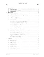
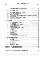
Page 1: ...INSTALLATION Ovation Dispensers OPERATION...
Page 3: ...November 2008 Part No 920559 Rev H Ovation Series Dispensers Installation Operation...
Page 4: ...November 2008 Part No 920559 Rev H...
Page 54: ...48 Part No 920559 Rev H November 2008...
Page 66: ...60 Part No 920559 Rev H November 2008...
Page 67: ...61 November 2008 Part No 920559 Rev H DISTANCE BETWEEN EYE BOLTS 33 1...
Page 68: ...62 Part No 920559 Rev H November 2008 INSTALLATION INSTRUCTION page 1 of 2 OVATION MODEL R13...
Page 69: ...63 November 2008 Part No 920559 Rev H INSTALLATION INSTRUCTION page 2 of 2 OVATION MODEL R13...
Page 70: ...64 Part No 920559 Rev H November 2008 INSTALLATION INSTRUCTION page 1 of 2 OVATION MODEL B23...
Page 71: ...65 November 2008 Part No 920559 Rev H INSTALLATION INSTRUCTION page 2 of 2 OVATION MODEL B23...
Page 74: ...68 Part No 920559 Rev H November 2008 INSTALLATION INSTRUCTION page 1 of 2 OVATION MODEL R11...
Page 75: ...69 November 2008 Part No 920559 Rev H INSTALLATION INSTRUCTION page 2 of 2 OVATION MODEL R11...
Page 76: ...70 November 2008 Part No 920559 Rev H...
Page 77: ...71 November 2008 Part No 920559 Rev H 2 7151 C TYPICAL SITE WIRING...
Page 78: ...72 Part No 920559 Rev H November 2008...
Page 80: ...74 Part No 920559 Rev H November 2008...
Page 81: ...75 November 2008 Part No 920559 Rev H APPENDIX D SITE INTERCONNECTION DIAGRAMS...
Page 82: ...76 Part No 920559 Rev H November 2008 Figure D 1 Backroom Installation Wayne Control System...
Page 84: ...78 Part No 920559 Rev H November 2008 Figure D 3 Pump Relay Installation Wiring Diagram...


