5
November 2008
Part No. 920559 Rev H
2
INSTALLATION
2.1 Inspect the Equipment
Examine the shipment immediately upon arrival to make certain there has been no damage or loss in
transit. Make sure that all the component parts, including keys and optional equipment (if any), are
accounted for. Check and save the Packing Slip, Bill of Lading, Invoice, and all other documents
included in the shipment. Damaged or lost equipment must be reported to the carrier. Any damage or
loss that may occur in transit is not covered under the Wayne/Dresser Warranty.
2.2 Island Construction, Dispenser Anchoring, and Piping
Product lines must avoid the creation of vapor in the lines and deliver a minimum pressure of 25 psi at
the dispenser inlet when all dispensers at the station dispensing the same product are operating.
A concrete foundation must be provided for the dispenser. Do not pour concrete around product lines or
electrical conduit risers.
Anchor bolts must be installed in the island to allow the dispenser to be bolted down in accordance with
NFPA requirements. The base of the dispenser contains six bolt hole slots (5/8 inch by 2 inch) for
anchoring the dispenser to the island.
Use of all anchoring locations is re-commended
.
Position
the anchor bolts in accordance with the dimensions shown on the Installation Instruction drawing for the
dispenser model. These drawings are located in Appendix B.
Vertical supply risers and electrical conduits must be located per the Installation Instruction for the
appropriate model. Proper height must be maintained to avoid undue stress on the dispenser.
For E85 Ovation models, product piping, pipe nipples, etc., containing Ethanol fuel must be Ethanol
compatible. See the information in Section 1.1 on page 1.
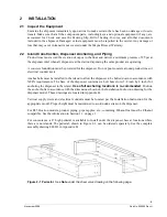
For convenience, a 6” high pedestal is available to install under the dispenser base at locations where
there are no islands. The pedestal, shown in Figure 2-1, can be ordered separately. See the complete
assembly drawing 888813 in Appendix B.
Figure 2-1 Pedestal.
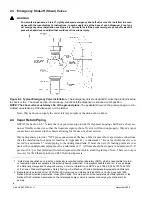
See
Note
under the shear valve drawing on the following page.
Summary of Contents for Ovation
Page 1: ...INSTALLATION Ovation Dispensers OPERATION...
Page 3: ...November 2008 Part No 920559 Rev H Ovation Series Dispensers Installation Operation...
Page 4: ...November 2008 Part No 920559 Rev H...
Page 54: ...48 Part No 920559 Rev H November 2008...
Page 66: ...60 Part No 920559 Rev H November 2008...
Page 67: ...61 November 2008 Part No 920559 Rev H DISTANCE BETWEEN EYE BOLTS 33 1...
Page 68: ...62 Part No 920559 Rev H November 2008 INSTALLATION INSTRUCTION page 1 of 2 OVATION MODEL R13...
Page 69: ...63 November 2008 Part No 920559 Rev H INSTALLATION INSTRUCTION page 2 of 2 OVATION MODEL R13...
Page 70: ...64 Part No 920559 Rev H November 2008 INSTALLATION INSTRUCTION page 1 of 2 OVATION MODEL B23...
Page 71: ...65 November 2008 Part No 920559 Rev H INSTALLATION INSTRUCTION page 2 of 2 OVATION MODEL B23...
Page 74: ...68 Part No 920559 Rev H November 2008 INSTALLATION INSTRUCTION page 1 of 2 OVATION MODEL R11...
Page 75: ...69 November 2008 Part No 920559 Rev H INSTALLATION INSTRUCTION page 2 of 2 OVATION MODEL R11...
Page 76: ...70 November 2008 Part No 920559 Rev H...
Page 77: ...71 November 2008 Part No 920559 Rev H 2 7151 C TYPICAL SITE WIRING...
Page 78: ...72 Part No 920559 Rev H November 2008...
Page 80: ...74 Part No 920559 Rev H November 2008...
Page 81: ...75 November 2008 Part No 920559 Rev H APPENDIX D SITE INTERCONNECTION DIAGRAMS...
Page 82: ...76 Part No 920559 Rev H November 2008 Figure D 1 Backroom Installation Wayne Control System...
Page 84: ...78 Part No 920559 Rev H November 2008 Figure D 3 Pump Relay Installation Wiring Diagram...


