29
November 2008
Part No. 920559 Rev H
3.11 Electronic Totalizer Readings
3.11.1 Totalizer Readings by Hose (Product) Position
Each fueling point of the dispenser maintains electronic totalizers for both money and volume. Dispens-
ers equipped for Cash/Credit operation also keep separate cash and credit totalizers by grade. Rather than
mechanical totalizers, each position has an electro-mechanical totalizer for each feedstock. See Figure 2-
4 for EMT locations.
Electronic totals are stored in statistical functions that are accessed using the IR remote control. The
totals for Side 1 are stored in statistical function
S01
and those for Side 2 are stored in statistical function
S02
. The associated sub-functions take the format
TN
, where
T
is the type of totals defined below and
nozzle postion
N
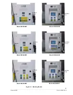
depends on the dispenser model as defined in Table 3-1.
T= totals type:1=Volume
2=Total Money
3=Credit
4=Cash
5=Serial Filling Mode Count
6=Stand Alone Mode Filling Count
For example, volume totals by hose position for Side 1 are accessed by examining the contents of statis-
tical function
S01.1N
while money totals are obtained by accessing
S01.2N
, where
N
is the hose position
number. For Side 2, the corresponding functions for these variables are
S02.1N
and
S02.2N,
respec-
tively.
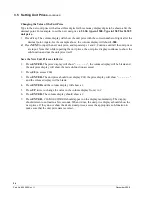
To read the electronic totalizers, perform the following steps using the IR remote.
Bold
type denote
remote control function;
italicized
type represents dispenser response:
Accessing the Totalizer Sub-function.
1. Press
ENTER
PASS 1
(enter password)
2. Press
ENTER
PASS 2
(enter password)
3. Press
ENTER.
The unit price display will show
F
4. Press either
UP
or
DOWN
to enter the statistics viewing mode. The unit price display will show S—
(indicating a number needs to be selected)
5. Press
01
to access
S01
6. Press
ENTER.
The unit price display will show
S01
indicating the function has been accessed.
7. Press
ENTER
to access the sub-functions of
S01.
The unit price display will show
1.11
and the sales
display shows the side 1, volume for nozzle position 1.
Consecutive presses of
NEXT
will advance to the next sub-function, incrementing the value of
N
by
(.
01)
. For example, pressing
NEXT
advances the statistical function to
S01.12
and the unit price display
will show
1.12
. The least significant six (6) digits of the data value appear on the volume display, while
higher order non-zero digits of the data value, if present, appear on the money display.
Summary of Contents for Ovation
Page 1: ...INSTALLATION Ovation Dispensers OPERATION...
Page 3: ...November 2008 Part No 920559 Rev H Ovation Series Dispensers Installation Operation...
Page 4: ...November 2008 Part No 920559 Rev H...
Page 54: ...48 Part No 920559 Rev H November 2008...
Page 66: ...60 Part No 920559 Rev H November 2008...
Page 67: ...61 November 2008 Part No 920559 Rev H DISTANCE BETWEEN EYE BOLTS 33 1...
Page 68: ...62 Part No 920559 Rev H November 2008 INSTALLATION INSTRUCTION page 1 of 2 OVATION MODEL R13...
Page 69: ...63 November 2008 Part No 920559 Rev H INSTALLATION INSTRUCTION page 2 of 2 OVATION MODEL R13...
Page 70: ...64 Part No 920559 Rev H November 2008 INSTALLATION INSTRUCTION page 1 of 2 OVATION MODEL B23...
Page 71: ...65 November 2008 Part No 920559 Rev H INSTALLATION INSTRUCTION page 2 of 2 OVATION MODEL B23...
Page 74: ...68 Part No 920559 Rev H November 2008 INSTALLATION INSTRUCTION page 1 of 2 OVATION MODEL R11...
Page 75: ...69 November 2008 Part No 920559 Rev H INSTALLATION INSTRUCTION page 2 of 2 OVATION MODEL R11...
Page 76: ...70 November 2008 Part No 920559 Rev H...
Page 77: ...71 November 2008 Part No 920559 Rev H 2 7151 C TYPICAL SITE WIRING...
Page 78: ...72 Part No 920559 Rev H November 2008...
Page 80: ...74 Part No 920559 Rev H November 2008...
Page 81: ...75 November 2008 Part No 920559 Rev H APPENDIX D SITE INTERCONNECTION DIAGRAMS...
Page 82: ...76 Part No 920559 Rev H November 2008 Figure D 1 Backroom Installation Wayne Control System...
Page 84: ...78 Part No 920559 Rev H November 2008 Figure D 3 Pump Relay Installation Wiring Diagram...


