31
November 2008
Part No. 920559 Rev H
3.11.3 Electro-Mechanical Totalizer Operation
Electro-Mechanical totalizers are standard on 3/Vista model dispensers. See Figure 2-4 for location.
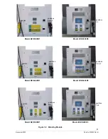
Electro-Mechanical totalizers are located on the junction box side of the dispenser. There is one totalizer for each
meter. The totalizer positions on the bezel relate to the meter position numbers shown in Table 3-2. The physical
position of the totalizers, left to right, on the bezel represent meter positions.
The totalizer shows seven digits and reads in whole units (gallons or liters). Fractional amounts that are left over
from a previous sale are stored in the dispenser computer. When the next sale of the same product ends, if the
fractional amounts from the new sale and previous sale(s) combined are one (1) whole unit or greater, the Elec-
tro-Mechanical totalizer is adjusted one whole increment; i.e., if five consecutive sales end with a fractional
amount of .2, the Electro-Mechanical totalizer will not account for the fractions until after the fifth sale.
Note:
A loose sheet of decals, part number 1-300051, with both preprinted (Low, Middle, High, Single) and
non-printed labels is supplied inside the electronic head of the dispenser for marking the
totalizer positions).
AA
Z
Y
X
8
7
6
5
M
M
M
M
4
3
2
1
Junction Box
Table 3-2 Meter Positions for Ovation Dispensers
Summary of Contents for Ovation
Page 1: ...INSTALLATION Ovation Dispensers OPERATION...
Page 3: ...November 2008 Part No 920559 Rev H Ovation Series Dispensers Installation Operation...
Page 4: ...November 2008 Part No 920559 Rev H...
Page 54: ...48 Part No 920559 Rev H November 2008...
Page 66: ...60 Part No 920559 Rev H November 2008...
Page 67: ...61 November 2008 Part No 920559 Rev H DISTANCE BETWEEN EYE BOLTS 33 1...
Page 68: ...62 Part No 920559 Rev H November 2008 INSTALLATION INSTRUCTION page 1 of 2 OVATION MODEL R13...
Page 69: ...63 November 2008 Part No 920559 Rev H INSTALLATION INSTRUCTION page 2 of 2 OVATION MODEL R13...
Page 70: ...64 Part No 920559 Rev H November 2008 INSTALLATION INSTRUCTION page 1 of 2 OVATION MODEL B23...
Page 71: ...65 November 2008 Part No 920559 Rev H INSTALLATION INSTRUCTION page 2 of 2 OVATION MODEL B23...
Page 74: ...68 Part No 920559 Rev H November 2008 INSTALLATION INSTRUCTION page 1 of 2 OVATION MODEL R11...
Page 75: ...69 November 2008 Part No 920559 Rev H INSTALLATION INSTRUCTION page 2 of 2 OVATION MODEL R11...
Page 76: ...70 November 2008 Part No 920559 Rev H...
Page 77: ...71 November 2008 Part No 920559 Rev H 2 7151 C TYPICAL SITE WIRING...
Page 78: ...72 Part No 920559 Rev H November 2008...
Page 80: ...74 Part No 920559 Rev H November 2008...
Page 81: ...75 November 2008 Part No 920559 Rev H APPENDIX D SITE INTERCONNECTION DIAGRAMS...
Page 82: ...76 Part No 920559 Rev H November 2008 Figure D 1 Backroom Installation Wayne Control System...
Page 84: ...78 Part No 920559 Rev H November 2008 Figure D 3 Pump Relay Installation Wiring Diagram...


