30
Part No. 920559 Rev H
November 2008
3.11.2 Totalizer Volume Readings by Meter Position
Meter volume totals are stored in statistical functions that are accessed using the remote control inter-
face. The totals for Side 1 are stored in function
S05
and those for Side 2 are stored in function
S06
. The
value of the meter totals are stored in the sub-functions that take the format
.M0
, where
M
is the meter
number. Assigned values of
M
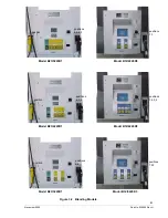
are shown in Table 3-2. For example,
M=5
for the high feedstock iMeter
located on Side 1 of a remote series blender. For Side 2 of the same meter,
M=1
.
Note:
There is no relationship between meter position and hose position. For example, in Table 3-1,
positions
N=1
and
N=5
are not
the high feedstock of a remote series blender used in the exam-
ple above.
Meter electronic totalizers are read by entering the Maintenance Mode and accessing the correct func-
tion and associated sub-functions. Perform the following steps using the remote control.
Bold
type
denote remote control function;
italicized
type represents dispenser response.
Accessing the Meter Volume Totalizer Sub-function for Side 1
1. Press
ENTER
PASS 1
(enter password)
2. Press
ENTER
PASS 2
(enter password)
3. Press
ENTER.
The unit price display will show
F
4. Press either
UP
or
DOWN
arrow to enter the statistics viewing mode. The unit price
display will show
S—
(indicating that a number needs to be selected)
5. Press
05
to access
S05
6. Press
ENTER.
The unit price display will show
S05
(indicating that the statistical
function has been accessed)
7. Press
ENTER
to access the sub-functions of
S05.
The unit price display will show
5.10
(note here that
M=1
)
Consecutive pressing of
NEXT
will allow access to the next sub-function, incrementing the value of
M
by (.
1)
. For example, to access
S05.20
, press
NEXT
. The unit price display will show
5.20
. The value
of the meter volume totals is shown in a format such that the least significant six (6) digits of the data
value appear on the volume display, while higher order non-zero digits of the data value, if present,
appear on the money display. Leading zeros appear as blanks.
Values for
M
are given in Table 3-2 for the dispenser models shown.
Quick Exit
1. Press the
CLEAR
key until the unit price display window shows S - - .
2. Press
ENTER
three times. This causes the maintenance mode task to immediately terminate.
Summary of Contents for Ovation
Page 1: ...INSTALLATION Ovation Dispensers OPERATION...
Page 3: ...November 2008 Part No 920559 Rev H Ovation Series Dispensers Installation Operation...
Page 4: ...November 2008 Part No 920559 Rev H...
Page 54: ...48 Part No 920559 Rev H November 2008...
Page 66: ...60 Part No 920559 Rev H November 2008...
Page 67: ...61 November 2008 Part No 920559 Rev H DISTANCE BETWEEN EYE BOLTS 33 1...
Page 68: ...62 Part No 920559 Rev H November 2008 INSTALLATION INSTRUCTION page 1 of 2 OVATION MODEL R13...
Page 69: ...63 November 2008 Part No 920559 Rev H INSTALLATION INSTRUCTION page 2 of 2 OVATION MODEL R13...
Page 70: ...64 Part No 920559 Rev H November 2008 INSTALLATION INSTRUCTION page 1 of 2 OVATION MODEL B23...
Page 71: ...65 November 2008 Part No 920559 Rev H INSTALLATION INSTRUCTION page 2 of 2 OVATION MODEL B23...
Page 74: ...68 Part No 920559 Rev H November 2008 INSTALLATION INSTRUCTION page 1 of 2 OVATION MODEL R11...
Page 75: ...69 November 2008 Part No 920559 Rev H INSTALLATION INSTRUCTION page 2 of 2 OVATION MODEL R11...
Page 76: ...70 November 2008 Part No 920559 Rev H...
Page 77: ...71 November 2008 Part No 920559 Rev H 2 7151 C TYPICAL SITE WIRING...
Page 78: ...72 Part No 920559 Rev H November 2008...
Page 80: ...74 Part No 920559 Rev H November 2008...
Page 81: ...75 November 2008 Part No 920559 Rev H APPENDIX D SITE INTERCONNECTION DIAGRAMS...
Page 82: ...76 Part No 920559 Rev H November 2008 Figure D 1 Backroom Installation Wayne Control System...
Page 84: ...78 Part No 920559 Rev H November 2008 Figure D 3 Pump Relay Installation Wiring Diagram...


