


Watlow EZ-ZONE
®
RMC Module
•
158
•
Chapter 7 Features
Ratio Control
Ratio control is commonly used to ensure that two
or more flows are kept at the same ratio even if the
flows are changing; especially useful in applications
that mix materials.
Applications of ratio control:
• Blending two or more flows to produce a mixture
with specified composition.
• Blending two or more flows to produce a mixture
with specified physical properties.
• Maintaining correct air and fuel mixture to com-
bustion.
controlled flow
of pigment
flow
transmitter
motorized
valve
Mixing Tank
flow
transmitter
mixed paint
uncontrolled
flow of
unmixed paint
Input 2
Input 1
Output 1
Motorized Valve Control
A motorized valve is used is to regulate the flow of
fluid which in turn impacts the loop process value. A
valve is opened or closed by closing contacts to drive
the value in the intended direction. This feature is
configured by selecting Motorized Valve as the func-
tion in the Setup Page, Special Output Function
menu. Source Function A is selected for either Heat
or Cool Power then entering the Valve Travel Time
and Deadband.
Lastly, program the outputs which will open and
close the valve. The algorithm will calculate Dead
Time which is the minimum on time that the valve
will travel once it is turned on in either the closed or
open direction. Dead Time = Valve Dead Band / 100
* Valve Travel Time.
Output 1 = Close
Temperature
Sensor
Gas Furnace
Output 2 = Open
Gas Flow
Valve
Actuator
®
Alarms
Alarms are activated when the output level, process
value or temperature leaves a defined range. A user
can configure how and when an alarm is triggered,
what action it takes and whether it turns off auto-
matically when the alarm condition is over.
Configure alarm outputs in the Setup Page before
setting alarm set points.
Alarms do not have to be assigned to an output.
Alarms can be monitored and controlled through the
front panel or by using software.
Process and Deviation Alarms
A process alarm uses one or two absolute set points
to define an alarm condition.
A deviation alarm uses one or two set points that
are defined relative to the control set point. High
and low alarm set points are calculated by adding or
subtracting offset values from the control set point.
If the set point changes, the window defined by the
alarm set points automatically moves with it.
Select the alarm type
[`A;ty]
via the Setup Page,
Alarm Menu.
Alarm Set Points
The alarm high set point defines the process value
or temperature that will trigger a high side alarm.
The alarm low set point defines the temperature that
will trigger a low side alarm. For deviation alarms,
a negative set point represents a value below closed
loop set point. A positive set point represents a value
above closed loop set point. View or change alarm set
points with Alarm Low
[`A;Lo]
and Alarm High Set
Points
[`A;hi]
(Operations Page, Alarm Menu).
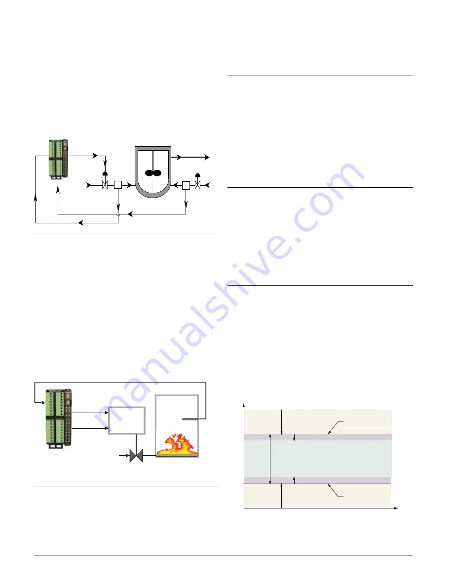
Alarm Hysteresis
An alarm state is triggered when the process value
reaches the alarm high or alarm low set point. Alarm
Hysteresis defines how far the process must return
into the normal operating range before the alarm can
be cleared.
Alarm Hysteresis is a zone inside each alarm set
point. This zone is defined by adding the hysteresis
value to the alarm low set point or subtracting the
hysteresis value from the alarm high set point. View
or change Alarm Hysteresis
[`A;hy]
via the Setup
Page, Alarm Menu.
Normal Operating Range
Low Side Alarm Range
High Side Alarm Range
Alarm High Set Point
Alarm Low Set Point
Time
Temperature
Alarm Set Points and Hysteresis
Alarm Hysteresis
Alarm Hysteresis


