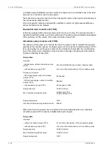
located in the ship's bottom is normally 65...75°C. To enable separation with a stopped engine
the heater capacity must be sufficient to maintain the required temperature without heat supply
from the engine.
Recommended oil temperature after the heater is 95°C.
It shall be considered that, while the engine is stopped in stand-by mode without LT water
circulation, the separator unit may be heating up the total amount of lubricating oil in the oil
tank to a value higher than the nominal one required at engine inlet, after lube oil cooler (see
Technical Data chapter). Higher oil temperatures at engine inlet than the nominal, may be
creating higher component wear and in worst conditions damages to the equipment and
generate alarm signal at engine start, or even a load reduction request to PMS.
The surface temperature of the heater must not exceed 150°C in order to avoid cooking of
the oil.
The heaters should be provided with safety valves and drain pipes to a leakage tank (so that
possible leakage can be detected).
Separator (2S01)
The separators should preferably be of a type with controlled discharge of the bowl to minimize
the lubricating oil losses.
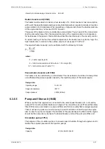
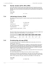
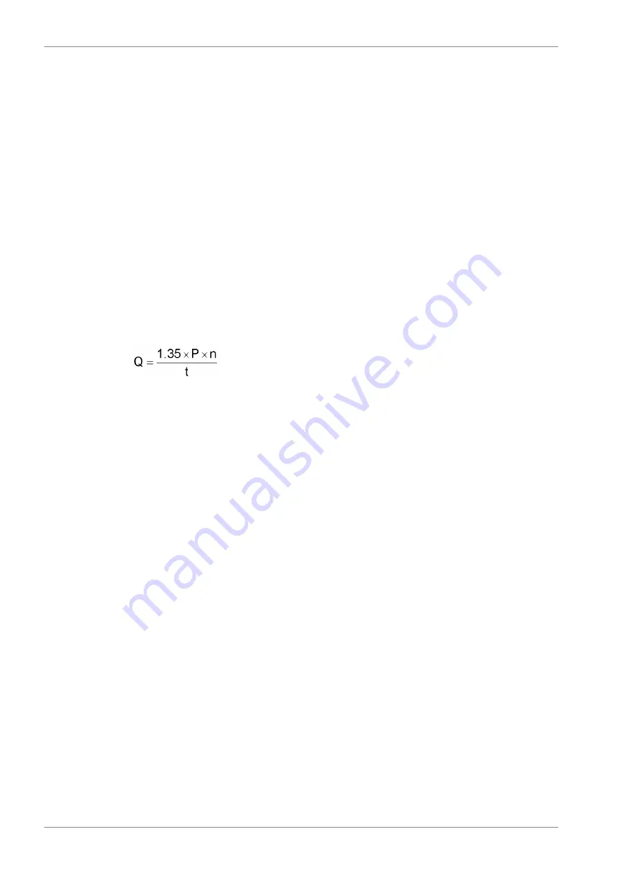
The service throughput Q [l/h] of the separator can be estimated with the formula:
where:
volume flow [l/h]
Q =
engine output [kW]
P =
5 for HFO, 4 for MDF
n =
operating time [h/day]: 24 for continuous separator operation, 23 for normal dimensioning
t =
Sludge tank (2T06)
The sludge tank should be located directly beneath the separators, or as close as possible
below the separators, unless it is integrated in the separator unit. The sludge pipe must be
continuously falling.
7.3.2
System oil tank (2T01)
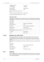
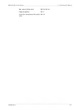
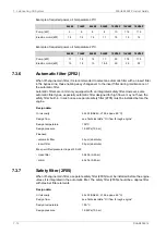
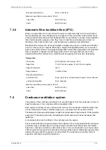
Recommended oil tank volume is stated in chapter Technical data.
The system oil tank is usually located beneath the engine foundation. The tank may not protrude
under the reduction gear or generator, and it must also be symmetrical in transverse direction
under the engine. The location must further be such that the lubricating oil is not cooled down
below normal operating temperature. Suction height is especially important with engine driven
lubricating oil pump. Losses in strainers etc. add to the geometric suction height. Maximum
suction ability of the pump is stated in chapter Technical data.
The pipe connection between the engine oil sump and the system oil tank must be flexible to
prevent damages due to thermal expansion. The return pipes from the engine oil sump must
end beneath the minimum oil level in the tank. Further on the return pipes must not be located
in the same corner of the tank as the suction pipe of the pump.
The suction pipe of the pump should have a trumpet shaped or conical inlet to minimise the
pressure loss. For the same reason the suction pipe shall be as short and straight as possible
and have a sufficient diameter. A pressure gauge shall be installed close to the inlet of the
7-10
DAAB605814
Wärtsilä 46F Product Guide
7. Lubricating Oil System
Summary of Contents for 46F Series
Page 1: ...Wärtsilä 46F PRODUCT GUIDE ...
Page 4: ...This page intentionally left blank ...
Page 8: ...This page intentionally left blank ...
Page 18: ...This page intentionally left blank ...
Page 86: ...This page intentionally left blank ...
Page 104: ...This page intentionally left blank ...
Page 154: ...This page intentionally left blank ...
Page 162: ...This page intentionally left blank ...
Page 170: ...This page intentionally left blank ...
Page 176: ...This page intentionally left blank ...
Page 194: ...This page intentionally left blank ...
Page 200: ...This page intentionally left blank ...
Page 202: ...This page intentionally left blank ...
Page 207: ...Fig 21 7 List of symbols DAAF406507 7 DAAB605814 21 5 21 ANNEX Wärtsilä 46F Product Guide ...

