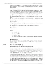
lubricating oil pump. The suction pipe shall further be equipped with a non-return valve of flap
type without spring. The non-return valve is particularly important with engine driven pump
and it must be installed in such a position that self-closing is ensured.
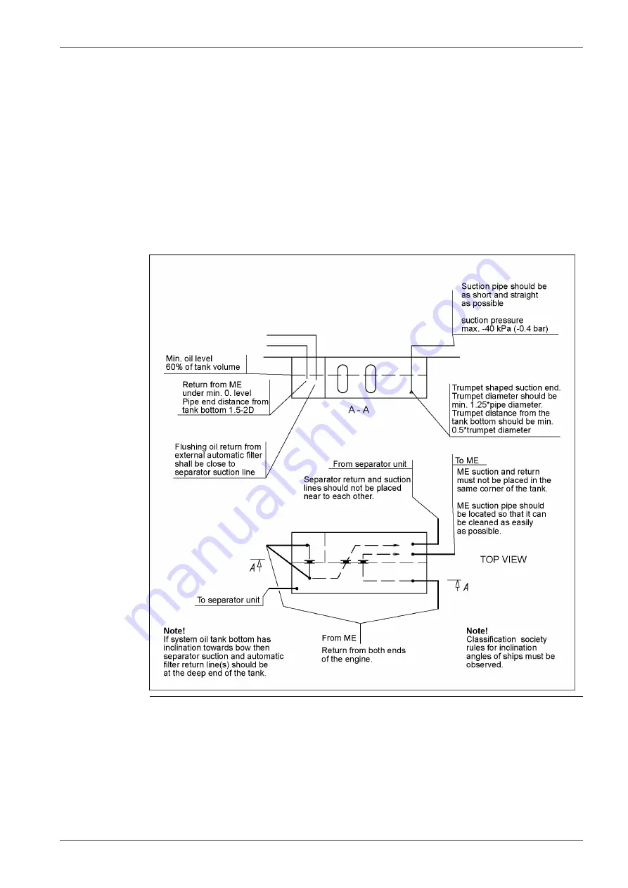
Suction and return pipes of the separator must not be located close to each other in the tank.
The ventilation pipe from the system oil tank may not be combined with crankcase ventilation
pipes.
It must be possible to raise the oil temperature in the tank after a long stop. In cold conditions
it can be necessary to have heating coils in the oil tank in order to ensure pumpability. The
separator heater can normally be used to raise the oil temperature once the oil is pumpable.
Further heat can be transferred to the oil from the preheated engine, provided that the oil
viscosity and thus the power consumption of the pre-lubricating oil pump does not exceed
the capacity of the electric motor.
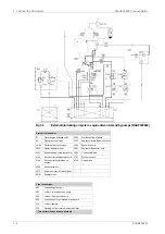
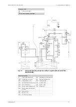
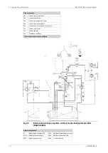
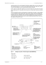
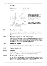
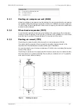
Fig 7-7
Example of system oil tank arrangement (DAAE007020e)
Design data:
see Technical data
Oil tank volume
75...80% of tank volume
Oil level at service
60% of tank volume
Oil level alarm
DAAB605814
7-11
7. Lubricating Oil System
Wärtsilä 46F Product Guide
Summary of Contents for 46F Series
Page 1: ...Wärtsilä 46F PRODUCT GUIDE ...
Page 4: ...This page intentionally left blank ...
Page 8: ...This page intentionally left blank ...
Page 18: ...This page intentionally left blank ...
Page 86: ...This page intentionally left blank ...
Page 104: ...This page intentionally left blank ...
Page 154: ...This page intentionally left blank ...
Page 162: ...This page intentionally left blank ...
Page 170: ...This page intentionally left blank ...
Page 176: ...This page intentionally left blank ...
Page 194: ...This page intentionally left blank ...
Page 200: ...This page intentionally left blank ...
Page 202: ...This page intentionally left blank ...
Page 207: ...Fig 21 7 List of symbols DAAF406507 7 DAAB605814 21 5 21 ANNEX Wärtsilä 46F Product Guide ...

