background image

DE

DE Constant

Speed

ME

CPP Con-

stant Speed

ME

CPP Variable

Speed

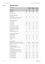
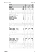
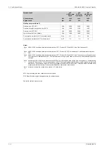
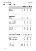
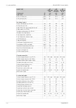
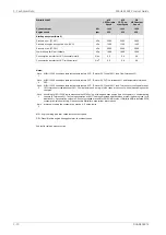
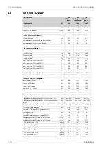
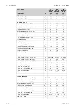
Wärtsilä 7L46F

1200

1200

1200

kW

Cylinder output

600

600

600

rpm

Engine speed

188.8

186.9

181.1

g/kWh

SFOC at 75% load (LFO)

197.9

192.2

183.1

g/kWh

SFOC at 50% load (LFO)

Lubricating oil system

500

500

500

kPa

Pressure before bearings, nom. (PT 201)

800

800

800

kPa

Pressure after pump, max.

40

40

40

kPa

Suction ability main pump, including pipe loss, max.

80

80

80

kPa

Priming pressure, nom. (PT 201)

56

56

56

°C

Temperature before bearings, nom. (TE 201)

75

75

75

°C

Temperature after engine, approx.

191

191

207

m

3

/h

Pump capacity (main), engine driven

179

179

207

m

3

/h

Pump capacity (main), electrically driven

150

150

150

m

3

/h

Oil flow through engine

45

45

45

m

3

/h

Priming pump capacity

15.0

15.0

15.0

m

3

Oil tank volume in separate system, min

0.7

0.7

0.7

g/kWh

Oil consumption at 100% load, approx.

1600

1600

1600

l/min

Crankcase ventilation flow rate at full load

0.4

0.4

0.4

kPa

Crankcase ventilation backpressure, max.

9.5

9.5

9.5

l

Oil volume in turning device

1.7

1.7

1.7

l

Oil volume in speed governor

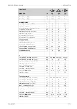
HT cooling water system

250 + static

250 + static

250 + static

kPa

Pressure at engine, after pump, nom. (PT 401)

530

530

530

kPa

Pressure at engine, after pump, max. (PT 401)

74

74

74

°C

Temperature before cylinders, approx. (TE 401)

91...95

91...95

91...95

°C

Temperature after charge air cooler, nom.

150

150

150

m

3

/h

Capacity of engine driven pump, nom.

150

150

150

kPa

Pressure drop over engine, total

100

100

100

kPa

Pressure drop in external system, max.

70...150

70...150

70...150

kPa

Pressure from expansion tank

1.3

1.3

1.3

m

3

Water volume in engine

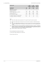
LT cooling water system

250 + static

250 + static

250 + static

kPa

Pressure at engine, after pump, nom. (PT 451)

530

530

530

kPa

Pressure at engine, after pump, max. (PT 451)

38

38

38

°C

Temperature before engine, max. (TE 451)

25

25

25

°C

Temperature before engine, min. (TE 451)

150

150

150

m

3

/h

Capacity of engine driven pump, nom.

50

50

50

kPa

Pressure drop over charge air cooler

20

20

20

kPa

Pressure drop over built-on lube oil cooler

30

30

30

kPa

Pressure drop over built-on temp. control valve

150

150

150

kPa

Pressure drop in external system, max.

70 ... 150

70 ... 150

70 ... 150

kPa

Pressure from expansion tank

0.4

0.4

0.4

m

3

Water volume in engine

3-6

DAAB605814

Wärtsilä 46F Product Guide

3. Technical Data

Summary of Contents for 46F Series

Page 1: ...Wärtsilä 46F PRODUCT GUIDE ...

Page 2: ...COMPLICATED TECHNICAL MATTERS SUITED ONLY FOR SPECIALISTS IN THE AREA AND THE DESIGN OF THE SUBJECT PRODUCTS IS SUBJECT TO REGULAR IMPROVEMENTS MODIFICATIONS AND CHANGES CONSEQUENTLY THE PUBLISHER AND COPYRIGHT OWNER OF THIS PUBLICATION CAN NOT ACCEPT ANY RESPONSIBILITY OR LIABILITY FOR ANY EVENTUAL ERRORS OR OMISSIONS IN THIS BOOKLET OR FOR DISCREPANCIES ARISING FROM THE FEATURES OF ANY ACTUAL IT...

Page 3: ...issues of the Wärtsilä 46F Product Guides Updates Published Issue Small updates in technical data section 05 09 2019 2 2019 Several updates throughout the product guide 26 07 2019 1 2019 Technical data updated 07 11 2017 3 2017 Technical data updated 27 06 2017 2 2017 Technical data updated 10 02 2017 1 2017 Flow diagrams updated other minor updates 27 06 2016 1 2016 Several updates throughout the...

Page 4: ...This page intentionally left blank ...

Page 5: ...in components and systems 4 5 4 3 Cross section of the engine 4 7 4 4 Overhaul intervals and expected life times 4 8 4 5 Engine storage 5 1 5 Piping Design Treatment and Installation 5 1 5 1 Pipe dimensions 5 2 5 2 Trace heating 5 2 5 3 Pressure class 5 3 5 4 Pipe class 5 3 5 5 Insulation 5 4 5 6 Local gauges 5 4 5 7 Cleaning procedures 5 5 5 8 Flexible pipe connections 5 6 5 9 Clamping of pipes 6...

Page 6: ...ation System 14 1 14 1 Technical data and system overview 14 3 14 2 Functions 14 5 14 3 Alarm and monitoring signals 14 5 14 4 Electrical consumers 14 7 14 5 Guideline for electrical and automation system 15 1 15 Foundation 15 1 15 1 Steel structure design 15 1 15 2 Engine mounting 16 1 16 Vibration and Noise 16 1 16 1 External forces and couples 16 2 16 2 Torque variations 16 2 16 3 Mass moments ...

Page 7: ... 1 19 1 Lifting the in line engine 19 2 19 2 Lifting the V engine 19 4 19 3 Engine components 20 1 20 Product Guide Attachments 21 1 21 ANNEX 21 1 21 1 Unit conversion tables 21 2 21 2 Collection of drawing symbols used in drawings DAAB605814 vii Table of contents Wärtsilä 46F Product Guide ...

Page 8: ...This page intentionally left blank ...

Page 9: ...tation 600 rpm Speed 11 6 m s Mean piston speed 1 1 Maximum continuous output Table 1 1 Maximum continuous output IMO Tier 2 Cylinder configuration bhp kW 9790 7200 W 6L46F 11420 8400 W 7L46F 13050 9600 W 8L46F 14680 10800 W 9L46F 19580 14400 W 12V46F 22840 16800 W 14V46F 26110 19200 W 16V46F The mean effective pressure Pe can be calculated using the following formula where mean effective pressure...

Page 10: ...rding to ISO 15550 2002 E The ISO standard reference conditions are 100 kPa total barometric pressure 25 C air temperature 30 relative humidity 25 C charge air coolant temperature Correction factors for the fuel oil consumption in other ambient conditions are given in standard ISO 15550 2002 E 1 3 Operation in inclined position Max inclination angles at which the engine will operate satisfactorily...

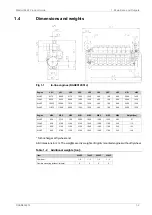
Page 11: ...WE5 WE3 WE2 WE1 HE6 HE5 HE4 Engine 97 385 1535 1480 1940 2905 790 2710 650 6L46F 113 340 1760 1480 1940 3130 1100 2700 650 7L46F 124 340 1760 1480 1940 3130 1100 2700 650 8L46F 140 340 1760 1480 1940 3130 1100 2700 650 9L46F Turbocharger at flywheel end All dimensions in mm The weights are dry weights of rigidly mounted engines without flywheel Table 1 2 Additional weights ton 9L46F 8L46F 7L46F 6L...

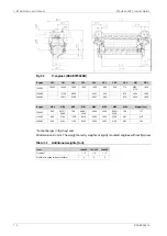
Page 12: ... 177 760 2825 3150 1820 2290 4040 4026 790 2975 2980 800 12V46F 216 892 3150 1820 2290 4678 1100 3134 800 14V46F 233 892 3150 1820 2290 4678 1100 3134 800 16V46F Turbocharger in flywheel end All dimensions in mm The weights are dry weights of rigidly mounted engines without flywheel Table 1 3 Additional weights ton 16V46F 14V46F 12V46F Item 1 2 1 2 1 2 Flywheel 3 3 3 Flexible mounting without limi...

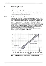
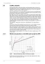
Page 13: ...engine load is derived from fuel rack position and actual engine speed not speed demand The propeller efficiency is highest at design pitch It is common practice to dimension the propeller so that the specified ship speed is attained with design pitch nominal engine speed and 85 output in the specified loading condition The power demand from a possible shaft generator or PTO must be taken into acc...

Page 14: ...r from this generator is ramped up to 100 during 10 minutes If the load sharing is based on speed drop the power management system ramps up the load on a recently connected generator according to the ramp preheated The emergency loading ramp can be used in critical situations e g to steer as fast as possible The emergency ramp can be activated manually or according to some predefined condition and...

Page 15: ...ad acceptance capability The maximum permissible load step for an engine that has attained normal operating temperature is 33 MCR The resulting speed drop is less than 10 and the recovery time to within 1 of the steady state speed at the new load level is max 5 seconds When electrical power is restored after a black out consumers are reconnected in groups which may cause significant load steps The...

Page 16: ...e engine must be loaded according to the indications reported in the Selective Catalytic Reduction system resetting operation section Max continuous operation time 3h in LFO At intervals of 3 operating hours the engine must be loaded according to the indications reported in the Selective Catalytic Reduction system resetting operation section Operation below 25 MCR Max continuous operation time 24h...

Page 17: ... in colder conditions at high loads suction air lower than 5 C provided that special provisions are considered to prevent too low HT water temperature and T C surge For start idling and low load operations Ch 2 3 suction air temperature shall be maintained at 5 C If necessary the preheating arrangement can be designed to heat the running engine capacity to be checked For further guidelines see cha...

Page 18: ...This page intentionally left blank ...

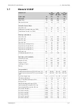
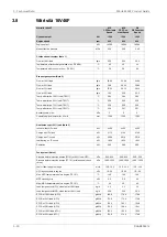
Page 19: ...s pressures etc for design of auxiliary systems Further design criteria for external equipment and system layouts are presented in the respective chapter Separate data is given for engines driving propellers ME and engines driving generators DE DAAB605814 3 1 3 Technical Data Wärtsilä 46F Product Guide ...

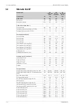
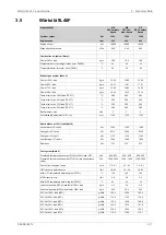
Page 20: ...3 912 912 912 kW Jacket water HT circuit 1572 1572 1542 kW Charge air HT circuit 762 762 786 kW Charge air LT circuit 732 732 732 kW Lubricating oil LT circuit 210 210 210 kW Radiation Fuel system Note 4 900 950 900 950 900 950 kPa Pressure before injection pumps PT 101 at 85 load 1000 1050 1000 1050 1000 1050 kPa Pressure before injection pumps PT 101 at idle speed check value 4 9 5 4 4 9 5 4 4 9...

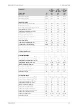
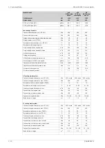
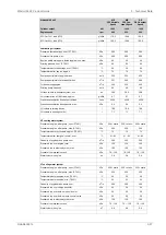
Page 21: ...volume in speed governor HT cooling water system 250 static 250 static 250 static kPa Pressure at engine after pump nom PT 401 530 530 530 kPa Pressure at engine after pump max PT 401 74 74 74 C Temperature before cylinders approx TE 401 91 95 91 95 91 95 C Temperature after charge air cooler nom 115 115 115 m3 h Capacity of engine driven pump nom 150 150 150 kPa Pressure drop over engine total 10...

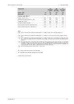
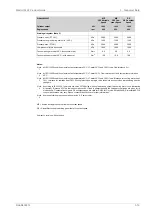
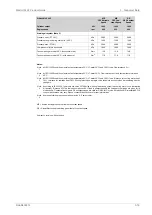
Page 22: ...ions ambient air temperature 25 C LT water 25 C and 100 load Tolerance for cooling water heat 10 tolerance for radiation heat 30 Fouling factors and a margin to be taken into account when dimensioning heat ex changers Note 3 According to ISO 15550 lower calorific value 42700 kJ kg with engine driven pumps two cooling water one lubricating oil pumps Tolerance 5 The fuel consumption at 85 load is gu...

Page 23: ... 3 1064 1064 1064 kW Jacket water HT circuit 1834 1834 1799 kW Charge air HT circuit 889 889 917 kW Charge air LT circuit 854 854 854 kW Lubricating oil LT circuit 245 245 245 kW Radiation Fuel system Note 4 900 950 900 950 900 950 kPa Pressure before injection pumps PT 101 at 85 load 1000 1050 1000 1050 1000 1050 kPa Pressure before injection pumps PT 101 at idle speed check value 5 7 6 3 5 7 6 3...

Page 24: ...volume in speed governor HT cooling water system 250 static 250 static 250 static kPa Pressure at engine after pump nom PT 401 530 530 530 kPa Pressure at engine after pump max PT 401 74 74 74 C Temperature before cylinders approx TE 401 91 95 91 95 91 95 C Temperature after charge air cooler nom 150 150 150 m3 h Capacity of engine driven pump nom 150 150 150 kPa Pressure drop over engine total 10...

Page 25: ...ions ambient air temperature 25 C LT water 25 C and 100 load Tolerance for cooling water heat 10 tolerance for radiation heat 30 Fouling factors and a margin to be taken into account when dimensioning heat ex changers Note 3 According to ISO 15550 lower calorific value 42700 kJ kg with engine driven pumps two cooling water one lubricating oil pumps Tolerance 5 The fuel consumption at 85 load is gu...

Page 26: ...1216 1216 1216 kW Jacket water HT circuit 2096 2096 2056 kW Charge air HT circuit 1016 1016 1048 kW Charge air LT circuit 976 976 976 kW Lubricating oil LT circuit 280 280 280 kW Radiation Fuel system Note 4 900 950 900 950 900 950 kPa Pressure before injection pumps PT101 at 85 load HFO 1000 1050 1000 1050 1000 1050 kPa Pressure before injection pumps PT 101 at idle speed check value 6 5 7 2 6 5 ...

Page 27: ...volume in speed governor HT cooling water system 250 static 250 static 250 static kPa Pressure at engine after pump nom PT 401 530 530 530 kPa Pressure at engine after pump max PT 401 74 74 74 C Temperature before cylinders approx TE 401 91 95 91 95 91 95 C Temperature after charge air cooler nom 150 150 150 m3 h Capacity of engine driven pump nom 150 150 150 kPa Pressure drop over engine total 10...

Page 28: ...ons ambient air temperature 25 C LT water 25 C and 100 load Tolerance for cooling water heat 10 tolerance for radiation heat 30 Fouling factors and a margin to be taken into account when dimensioning heat ex changers Note 3 According to ISO 15550 lower calorific value 42700 kJ kg with engine driven pumps two cooling water one lubricating oil pumps Tolerance 5 The fuel consumption at 85 load is gua...

Page 29: ... 1368 1368 1368 kW Jacket water HT circuit 2358 2358 2313 kW Charge air HT circuit 1143 1143 1179 kW Charge air LT circuit 1098 1098 1098 kW Lubricating oil LT circuit 315 315 315 kW Radiation Fuel system Note 4 900 950 900 950 900 950 kPa Pressure before injection pumps PT101 at 85 load HFO 1000 1050 1000 1050 1000 1050 kPa Pressure before injection pumps PT 101 at idle speed check value 7 3 8 1 ...

Page 30: ... volume in speed governor HT cooling water system 250 static 250 static 250 static kPa Pressure at engine after pump nom PT 401 530 530 530 kPa Pressure at engine after pump max PT 401 74 74 74 C Temperature before cylinders approx TE 401 91 95 91 95 91 95 C Temperature after charge air cooler nom 180 180 180 m3 h Capacity of engine driven pump nom 150 150 150 kPa Pressure drop over engine total 1...

Page 31: ...tions ambient air temperature 25 C LT water 25 C and 100 load Tolerance for cooling water heat 10 tolerance for radiation heat 30 Fouling factors and a margin to be taken into account when dimensioning heat ex changers Note 3 According to ISO 15550 lower calorific value 42700 kJ kg with engine driven pumps two cooling water one lubricating oil pumps Tolerance 5 The fuel consumption at 85 load is g...

Page 32: ...824 1824 1800 kW Jacket water HT circuit 3108 3108 3084 kW Charge air HT circuit 1512 1512 1572 kW Charge air LT circuit 1464 1464 1464 kW Lubricating oil LT circuit 420 420 420 kW Radiation Fuel system Note 4 900 950 900 950 900 950 kPa Pressure before injection pumps PT101 at 85 load HFO 1000 1050 1000 1050 1000 1050 kPa Pressure before injection pumps PT 101 at idle speed check value 9 8 10 8 9...

Page 33: ...l volume in speed governor HT cooling water system 250 static 250 static 250 static kPa Pressure at engine after pump nom PT 401 530 530 530 kPa Pressure at engine after pump max PT 401 74 74 74 C Temperature before cylinders approx TE 401 91 95 91 95 91 95 C Temperature after charge air cooler nom 210 210 210 m3 h Capacity of engine driven pump nom 150 150 150 kPa Pressure drop over engine total ...

Page 34: ...ditions ambient air temperature 25 C LT water 25 C and 100 load Tolerance for cooling water heat 10 tolerance for radiation heat 30 Fouling factors and a margin to be taken into account when dimensioning heat ex changers Note 3 According to ISO 15550 lower calorific value 42700 kJ kg with engine driven pumps two cooling water one lubricating oil pumps Tolerance 5 The fuel consumption at 85 load is...

Page 35: ...8 2128 2100 kW Jacket water HT circuit 3626 3626 3598 kW Charge air HT circuit 1764 1764 1834 kW Charge air LT circuit 1708 1708 1708 kW Lubricating oil LT circuit 490 490 490 kW Radiation Fuel system Note 4 900 950 900 950 900 950 kPa Pressure before injection pumps PT101 at 85 load HFO 1000 1050 1000 1050 1000 1050 kPa Pressure before injection pumps PT 101 at idle speed check value 11 4 12 6 11...

Page 36: ...l volume in speed governor HT cooling water system 250 static 250 static 250 static kPa Pressure at engine after pump nom PT 401 530 530 530 kPa Pressure at engine after pump max PT 401 74 74 74 C Temperature before cylinders approx TE 401 91 95 91 95 91 95 C Temperature after charge air cooler nom 240 240 240 m3 h Capacity of engine driven pump nom 150 150 150 kPa Pressure drop over engine total ...

Page 37: ...ditions ambient air temperature 25 C LT water 25 C and 100 load Tolerance for cooling water heat 10 tolerance for radiation heat 30 Fouling factors and a margin to be taken into account when dimensioning heat ex changers Note 3 According to ISO 15550 lower calorific value 42700 kJ kg with engine driven pumps two cooling water one lubricating oil pumps Tolerance 5 The fuel consumption at 85 load is...

Page 38: ...2 2432 2400 kW Jacket water HT circuit 4144 4144 4112 kW Charge air HT circuit 2016 2016 2096 kW Charge air LT circuit 1952 1952 1952 kW Lubricating oil LT circuit 560 560 560 kW Radiation Fuel system Note 4 900 950 900 950 900 950 kPa Pressure before injection pumps PT101 at 85 load HFO 1000 1050 1000 1050 1000 1050 kPa Pressure before injection pumps PT 101 at idle speed check value 13 0 14 4 13...

Page 39: ...l volume in speed governor HT cooling water system 250 static 250 static 250 static kPa Pressure at engine after pump nom PT 401 530 530 530 kPa Pressure at engine after pump max PT 401 74 74 74 C Temperature before cylinders approx TE 401 91 95 91 95 91 95 C Temperature after charge air cooler nom 280 280 280 m3 h Capacity of engine driven pump nom 150 150 150 kPa Pressure drop over engine total ...

Page 40: ...ditions ambient air temperature 25 C LT water 25 C and 100 load Tolerance for cooling water heat 10 tolerance for radiation heat 30 Fouling factors and a margin to be taken into account when dimensioning heat ex changers Note 3 According to ISO 15550 lower calorific value 42700 kJ kg with engine driven pumps two cooling water one lubricating oil pumps Tolerance 5 The fuel consumption at 85 load is...

Page 41: ...d radial bearing for the camshaft drive and flywheel The bearing housing of the intermediate gear is integrated in the engine block The cooling water is distributed around the cylinder liners with water distribution rings at the lower end of the cylinder collar There is no wet space in the engine block around the cylinder liner which eliminates the risk of water leakage into the crankcase 4 2 2 Cr...

Page 42: ...e optimum running conditions for the piston and piston rings The liner material is a special grey cast iron alloy developed for excellent wear resistance and high strength Accurate temperature control is achieved with precisely positioned longitudinal cooling water bores An anti polishing ring removes deposits from piston top land which eliminates increased lubricating oil consumption due to bore ...

Page 43: ...rmally by the speed control 4 2 12 Lubricating oil system The engine is equipped with a dry oil sump In the standard configuration the engine is also equipped with an engine driven lubricating oil pump located in free end and a lubricating oil module located in the opposite end to the turbocharger The lubricating oil module consists of an oil cooler with temperature control valves and an automatic...

Page 44: ...ular embedded automation system Wärtsilä Unified Controls UNIC The system version UNIC C2 has a hardwired interface for control functions and a bus communication interface for alarm and monitoring An engine safety module and a local control panel mounted on the engine The engine safety module handles fundamental safety for example overspeed and low lubricating oil pressure shutdown The safety modu...

Page 45: ...4 3 Cross section of the engine Fig 4 2 Cross section of the in line engine DAAB605814 4 5 4 Description of the Engine Wärtsilä 46F Product Guide ...

Page 46: ...Fig 4 3 Cross section of the V engine 4 6 DAAB605814 Wärtsilä 46F Product Guide 4 Description of the Engine ...

Page 47: ...t crown dismantling one 24000 28000 32000 Piston skirt crown dismantling all Piston rings 12000 16000 20000 Cylinder liner Antipolishing ring 12000 16000 20000 Gudgeon pin inspection 12000 16000 20000 Gudgeon pin bearing inspection Big end bearing 12000 16000 20000 Big end bearing inspection of one 36000 36000 36000 Big end bearing replacement of all Main bearing 12000 16000 20000 Main bearing ins...

Page 48: ...dgeon pin inspection 36000 36000 36000 Gudgeon pin bearing inspection 36000 36000 36000 Big end bearing Big end bearing inspection of one Big end bearing replacement of all 36000 36000 36000 Main bearing Main bearing inspection of one Main bearing replacement of all 60000 60000 60000 Camshaft bearing Camshaft bearing inspection of one Camshaft bearing replacement of all Turbocharger inspection cle...

Page 49: ...pipes shall have continuous slope Vent pipes shall be continuously rising Flanged connections shall be used cutting ring joints for precision tubes Maintenance access and dismounting space of valves coolers and other devices shall be taken into consideration Flange connections and other joints shall be located so that dismounting of the equipment can be made with reasonable effort 5 1 Pipe dimensi...

Page 50: ...ssure stated in chapter Compressed air system due to pressure drop in the pipeline 5 2 Trace heating The following pipes shall be equipped with trace heating steam thermal oil or electrical It shall be possible to shut off the trace heating All heavy fuel pipes All leak fuel and filter flushing pipes carrying heavy fuel 5 3 Pressure class The pressure class of the piping should be higher than or e...

Page 51: ...0 PN16 PN25 PN40 etc 5 4 Pipe class Classification societies categorize piping systems in different classes DNV or groups ABS depending on pressure temperature and media The pipe class can determine Type of connections to be used Heat treatment Welding procedure Test method Systems with high design pressures and temperatures and hazardous media belong to class I or group I others to II or III as a...

Page 52: ...ng Methods System A B C D F Fuel oil A B C D F Lubricating oil A B C Starting air A B C Cooling water A B C Exhaust gas A B C Charge air 1 In case of carbon steel pipes Methods applied during prefabrication of pipe spools A Washing with alkaline solution in hot water at 80 C for degreasing only if pipes have been greased B Removal of rust and scale with steel brush not required for seamless precis...

Page 53: ...n onboard Pipes are pickled in an acid solution of 10 hydrochloric acid and 10 formaline inhibitor for 4 5 hours rinsed with hot water and blown dry with compressed air After acid treatment the pipes are treated with a neutralizing solution of 10 caustic soda and 50 grams of trisodiumphosphate per litre of water for 20 minutes at 40 50 C rinsed with hot water and blown dry with compressed air Grea...

Page 54: ...ed flexible connections carrying flammable fluids or compressed air have to be type approved 5 9 Clamping of pipes It is very important to fix the pipes to rigid structures next to flexible pipe connections in order to prevent damage caused by vibration The following guidelines should be applied Pipe clamps and supports next to the engine must be very rigid and welded to the steel structure of the...

Page 55: ...ow thermal expansion of the pipe Supports should never be welded directly to the pipe Either pipe clamps or flange supports should be used for flexible connection Examples of flange support structures are shown in Figure 5 2 A typical pipe clamp for a fixed support is shown in Figure 5 3 Pipe clamps must be made of steel plastic clamps or similar may not be used Fig 5 2 Flange supports of flexible...

Page 56: ...Fig 5 3 Pipe clamp for fixed support V61H0842A 5 8 DAAB605814 Wärtsilä 46F Product Guide 5 Piping Design Treatment and Installation ...

Page 57: ...t can prevent the use in engines unless the fuel can be cooled down enough to meet the min injection viscosity limit of the engine DMA A high quality distillate generally designated MGO Marine Gas Oil in the marine field DFA A similar quality distillate fuel compared to DMA category fuels but a presence of max 7 0 v v of Fatty acid methyl ester FAME is allowed DMZ A high quality distillate general...

Page 58: ...on stability ASTM D7963 or IP 579 7 0 7 0 7 0 Max v v Fatty acid methyl ester FAME e ISO 10370 0 30 0 30 0 30 Max m m Carbon residue Micro method on 10 distillation residue ISO 10370 0 30 Max m m Carbon residue Micro method ISO 3015 Report Report 16 Max C winter Cloud point f 16 summer IP 309 or IP 612 Report Report Max C winter Cold filter plugging point f summer ISO 3016 0 6 6 Max C winter Pour ...

Page 59: ...uels with a sulphur content below 500 mg kg 0 050 m m Additional notes not included in the ISO 8217 2017 E standard i Low min viscosity of 1 400 mm s can prevent the use ISO F DMX category fuels in Wärtsilä 4 stroke engines unless a fuel can be cooled down enough to meet the specified min injection viscosity limit j Allowed kinematic viscosity before the injection pumps for this engine type is 2 0...

Page 60: ...a Kinematic viscosity bef injection pumps c ISO 3104 80 00 30 00 10 00 mm2 s a Kinematic viscosity at 50 C max ISO 3675 or ISO 12185 975 0 960 0 920 0 kg m3 Density at 15 C max ISO 8217 Annex F 860 860 850 CCAI max e ISO 8574 or ISO 14596 0 10 0 10 0 10 m m Sulphur max b ISO 2719 60 0 60 0 60 0 C Flash point min IP 570 2 00 2 00 2 00 mg kg Hydrogen sulfide max ASTM D664 2 5 2 5 2 5 mg KOH g Acid n...

Page 61: ...ne fuels ignition properties especially concerning fuels originating from modern and more complex refinery processes f Sodium contributes to hot corrosion on exhaust valves when combined with high sulphur and vanadium contents Sodium also strongly contributes to fouling of the exhaust gas turbine blading at high loads The aggressiveness of the fuel depends on its proportions of sodium and vanadium...

Page 62: ...ory require ments m m Sulphur max c g ISO 2719 60 0 60 0 C Flash point min IP 570 2 00 2 00 mg kg Hydrogen sulfide max ASTM D664 2 5 2 5 mg KOH g Acid number max ISO 10307 2 0 10 0 10 m m Total sediment aged max ISO 10370 20 00 15 00 m m Carbon residue micro method max ASTM D3279 14 0 8 0 m m Asphaltenes max d ISO 3016 30 30 C Pour point upper max e ISO 3733 or ASTM D6304 C d 0 50 0 50 V V Water m...

Page 63: ...ecially concerning fuels originating from modern and more complex refinery processes g Sodium contributes to hot corrosion on exhaust valves when combined with high sulphur and vanadium contents Sodium also strongly contributes to fouling of the exhaust gas turbine blading at high loads The aggressiveness of the fuel depends on its proportions of sodium and vanadium but also on the total amount of...

Page 64: ...101 Engine speed 1 ST173 Fuel oil leakage clean primary LS103A Engine speed 2 ST174 Fuel oil leakage clean secondary LS106A Engine speed primary ST196P Fuel oil leakage dirty fuel DE LS108A Engine speed secondary ST196S Stop lever in stop position GS171 Fuel rack position GT165 2 Turning gear engaged GS792 Fuel rack control CV161 Pipe connections Leak fuel drain clean fuel DE 103AD Fuel inlet 101 ...

Page 65: ... leakage FE LS107A B Engine speed back up ST196S Fuel oil dirty leakage DE LS108A B Turning gear engaged GS792 Fuel rack actuator CV161 Electric motor for turning gear M755 Fuel rack position GT165 2 Drive unit for CV178 U178 Stop lever in stop position GS171 Size Pipe connections DN32 Fuel inlet 101A B DN32 Fuel outlet 102A B DN25 Leak fuel drain clean fuel 103A B DN25 Leak fuel drain dirty fuel ...

Page 66: ...stance next to the engine See chapter Piping design treatment and installation A connection for compressed air should be provided before the engine together with a drain from the fuel return line to the clean leakage fuel or overflow tank With this arrangement it is possible to blow out fuel from the engine prior to maintenance work to avoid spilling NOTE In multiple engine installations where sev...

Page 67: ...ed 6 3 2 Fuel heating requirements HFO Heating is required for Bunker tanks settling tanks day tanks Pipes trace heating Separators Fuel feeder booster units To enable pumping the temperature of bunker tanks must always be maintained 5 10 C above the pour point typically at 40 50 C The heating coils can be designed for a temperature of 60 C The tank heating capacity is determined by the heat loss ...

Page 68: ...n parallel to the nearest viscosity temperature line in the diagram Example 2 Known viscosity 60 cSt at 50 C K The following can be read along the dotted line viscosity at 80 C 20 cSt temperature at fuel injection pumps 74 87 C separating temperature 86 C minimum bunker tank temperature 28 C 6 3 3 Fuel tanks The fuel oil is first transferred from the bunker tanks to settling tanks for initial sepa...

Page 69: ...the fuel feed pumps If black out starting with MDF from a gravity tank is foreseen then the tank must be located at least 15 m above the engine crankshaft 6 3 3 3 Leak fuel tank clean fuel 1T04 Clean leak fuel is drained by gravity from the engine The fuel should be collected in a separate clean leak fuel tank from where it can be pumped to the day tank and reused without separation The pipes from...

Page 70: ... with densities exceeding 991 kg m3 at 15 C In this case the main and stand by separators should be run in parallel When separators with gravity disc are used then each stand by separator should be operated in series with another separator so that the first separator acts as a purifier and the second as clarifier This arrangement can be used for fuels with a density of max 991 kg m3 at 15 C The se...

Page 71: ...ator feed pumps 1P02 Feed pumps should be dimensioned for the actual fuel quality and recommended throughput of the separator The pump should be protected by a suction strainer mesh size about 0 5 mm An approved system for control of the fuel feed rate to the separator is required MDF HFO Design data 0 5 MPa 5 bar 0 5 MPa 5 bar Design pressure DAAB605814 6 15 6 Fuel Oil System Wärtsilä 46F Product...

Page 72: ... heater C ΔT For heavy fuels ΔT 48 C can be used i e a settling tank temperature of 50 C Fuels having a viscosity higher than 5 cSt at 50 C require pre heating before the separator The heaters to be provided with safety valves and drain pipes to a leakage tank so that the possible leakage can be detected 6 3 4 5 Separator 1S01 1S02 Based on a separation time of 23 or 23 5 h day the service through...

Page 73: ...nless it is integrated in the separator unit The sludge pipe must be continuously falling 6 3 5 Fuel feed system MDF installations Fig 6 5 Example of fuel oil system MDF DAAF42878 System components Circulation pump MDF 1P03 Diesel engine Wärtsilä L46F 01 Leak fuel tank clean fuel 1T04 Adaptor 02 Day tank MDF 1T06 Cooler MDF 1E04 Leak fuel tank dirty fuel 1T07 Fine filter MDF 1F05 Quick closing val...

Page 74: ...7 Leak fuel drain dirty fuel 104 Flow meter MDF 1I03 Circulation pump MDF 1P03 Leak fuel tank clean fuel 1T04 Day tank MDF 1T06 Leak fuel tank dirty fuel 1T07 Quick closing valve 1V10 If the engines are to be operated on MDF only heating of the fuel is normally not necessary In such case it is sufficient to install the equipment listed below Some of the equipment listed below is also to be install...

Page 75: ...the day tank before the return fuel tank A fuel oil cooler is usually required with a return fuel tank The total resistance of the flow meter and the suction strainer must be small enough to ensure a positive static pressure of about 30 kPa on the suction side of the circulation pump There should be a bypass line around the consuption meter For mechanical flowmeter the bypass line should open auto...

Page 76: ...load and 0 5 kW cyl at idle Heat to be dissipated 80 kPa 0 8 bar Max pressure drop fuel oil 60 kPa 0 6 bar Max pressure drop water min 15 Margin heat rate fouling 50 150 C Design temperature MDF HFO installa tion 6 3 5 5 Black out start Diesel generators serving as the main source of electrical power must be able to resume their operation in a black out situation by means of stored energy Dependin...

Page 77: ...it 1E03 De aeration tank Booster Unit 1T08 Cooler MDF 1E04 Change over valve 1V01 Safety filter HFO 1F03 Pressure control valve Booster Unit 1V03 Suction filter Booster Unit 1F06 Venting valve Booster Unit 1V07 Automatic filter Booster Unit 1F08 Quick closing valve Fuel oil tank 1V10 Flow meter Booster Unit 1I01 Change over valve for leak fuel 1V13 Viscosity meter Booster Unit 1I02 Pipe connection...

Page 78: ...oler MDF 1E04 Change over valve 1V01 Safety filter HFO 1F03 Pressure control valve Booster unit 1V03 Suction filter Booster Unit 1F06 Overflow valve HFO MDF 1V05 Automatic filter Booster Unit 1F08 Venting valve Booster unit 1V07 Flow meter Booster Unit 1I01 Quick closing valve Fuel oil tank 1V10 Viscosity meter Booster Unit 1I02 Change over valve for leak fuel 1V13 Feeder booster unit 1N01 Pipe co...

Page 79: ... 1N01 shall be installed On multiple installation of W46DF engines it s possible to install a single feeder booster unit 1N01 followed by one individual circulation pump before each W46DF engine 1P12 It s anyhow recommended to consider redundancy of feeder booster unit 1N01 for higher installation reliability In addition the following guidelines apply Twin screw vessels with two engines should hav...

Page 80: ...ssembled All HFO pipes are insulated and provided with trace heating Fig 6 9 Feeder booster unit example DAAE006659 Fuel feed pump booster unit 1P04 The feed pump maintains the pressure in the fuel feed system It is recommended to use a screw pump as feed pump The capacity of the feed pump must be sufficient to prevent pressure drop during flushing of the automatic filter A suction strainer with a...

Page 81: ...utomatic filter must be installed before the heater between the feed pump and the de aeration tank and it should be equipped with a heating jacket Overheating temperature exceeding 100 C is however to be prevented and it must be possible to switch off the heating for operation on MDF Design data According to fuel specification Fuel viscosity 100 C Design temperature If fuel viscosity is higher tha...

Page 82: ... the fuel in the system it also maintains correct viscosity and keeps the piping and the injection pumps at operating temperature Design data Capacity LFO 2cSt HFO 20cSt See chapter Technical data single engine without circulation pumps 1P12 15 more than total capacity of all circulation pumps with circulation pumps 1P12 Frequency Converter Not needed HFO single engine without circulation pumps 1P...

Page 83: ...ut 15 margin l h Q temperature rise in heater C ΔT Viscosimeter booster unit 1I02 The heater is to be controlled by a viscosimeter The viscosimeter should be of a design that can withstand the pressure peaks caused by the injection pumps of the diesel engine Design data 0 50 cSt Operating range 180 C Design temperature 4 MPa 40 bar Design pressure 6 3 6 5 Pump and filter unit 1N03 When more than t...

Page 84: ...um permitted pressure drops at 14 cSt 20 kPa 0 2 bar clean filter 80 kPa 0 8 bar alarm 6 3 6 6 Overflow valve HFO 1V05 When several engines are connected to the same feeder booster unit an overflow valve is needed between the feed line and the return line The overflow valve limits the maximum pressure in the feed line when the fuel lines to a parallel engine are closed for maintenance purposes The...

Page 85: ... a temporary pipe or hose on the installation side All filter inserts are removed except in the flushing filter of course The automatic filter and the viscosimeter should be bypassed to prevent damage The fineness of the flushing filter should be 35 μm or finer DAAB605814 6 29 6 Fuel Oil System Wärtsilä 46F Product Guide ...

Page 86: ...This page intentionally left blank ...

Page 87: ... m m Lubricating oil BN Fuel standard Category 3 50 or statuatory require ments 30 55 GRADE NO 4D GRADE NO 5 6 DMC RMA10 RMK55 DC A30 K700 RMA10 RMK700 ASTM D 975 17 ASTM D 396 17 BS MA 100 1996 CIMAC 2003 ISO 8217 2017 E C Sulphur content can be also higher than 3 50 m m It is recommended to use in the first place BN 50 55 lubricants when operating on residual fuel This recommendation is valid es...

Page 88: ... SAE 30 or SAE 40 is acceptable in normal operating conditions Usually the same oil as in the engine can be used At low ambient temperatures it may be necessary to use a multigrade oil e g SAE 5W 40 to ensure proper operation during start up with cold oil 7 1 3 Oil in turning device It is recommended to use EP gear oils viscosity 400 500 cSt at 40 C ISO VG 460 An updated list of approved oils is s...

Page 89: ...let at DE A bank from oil sump 202 AD Lube oil from eldriven pump 208 Lubricating oil outlet at DE B bank from oil sump 202 BD Lube oil to external filter 209 Lubricating oil inlet to engine driven pump 203 Lube oil from cooler 212 Lubricating oil from priming pump 206 Lube oil sample 219 Fig 7 2 Internal lubricating oil system V engine DAAR011169D System components Lubricating oil automatic filte...

Page 90: ...ections Lubricating oil outlet from oil sump 202 Lubricating oil inlet to engine driven pump 203 Lubricating oil from priming pump 206 Lubricating oil from electric driven pump 208 Flushing oil from internal automatic filter 223 Sample 219 Crankcase air vent 701A B The oil sump is of dry sump type There are two oil outlets at each end of the engine One outlet at the free end and both outlets at th...

Page 91: ... oil pump 2F01 Condensate trap 2S02 Suction filter Separator unit 2F03 System oil tank 2T01 Suction strainer Pre lubricating oil pump 2F04 Sludge tank 2T06 Suction strainer Stand by pump 2F06 Automatic filter LO back flush 2F13 Pipe connections Lubricating oil from electric driven pump 208 Lubricating oil outlet 202 Flushing oil from internal automatic filter 223 Lubricating oil to engine driven p...

Page 92: ...ion strainer main lube pump 2F01 System oil tank 2T01 Suction strainer separator unit 2F03 Sludge tank 2T06 Suction strainer prelube oil pump 2F04 Suction strainer 2F06 Automatic filter LO back flush 2F13 Separator unit 2N01 Pipe connections Lubricating oil outlet 202 Lube oil to engine driven pump 203 Lube oil from priming pump 206 Lubricating oil from electric driven pump 208 Lube oil sample 219...

Page 93: ...F 01 Separator Separator unit 2S01 Flexible pipe connections 2H0X Condensate trap 2S02 Heater separator unit 2E02 Stand by pump 2P04 Suction strainer main lube pump 2F01 System oil tank 2T01 Automatic filter LO 2F02 Sludge tank 2T06 Suction strainer separator unit 2F03 Suction strainer pre lubricating oil pump 2F04 Safety filter LO 2F05 Separator unit 2N01 Pre lubricating oil pump 2P02 DAAB605814 ...

Page 94: ...sample 219 Crankcase ventilation 701 Two outlets in each end are available Fig 7 6 External lubricating oil system without engine built automatic filter DAAF423926 System components Separator pump Separator unit 2P03 Diesel engine Wärtsilä L46F 01 Separator Separator unit 2S01 Flexible pipe connections 2H0X Condensate trap 2S02 Heater separator unit 2E02 7 8 DAAB605814 Wärtsilä 46F Product Guide 7...

Page 95: ...e sufficient Separators are usually supplied as pre assembled units Typically lubricating oil separator units are equipped with Feed pump with suction strainer and safety valve Preheater Separator Control cabinet The lubricating oil separator unit may also be equipped with an intermediate sludge tank and a sludge pump which offers flexibility in placement of the separator since it is not necessary...

Page 96: ... 23 for normal dimensioning t Sludge tank 2T06 The sludge tank should be located directly beneath the separators or as close as possible below the separators unless it is integrated in the separator unit The sludge pipe must be continuously falling 7 3 2 System oil tank 2T01 Recommended oil tank volume is stated in chapter Technical data The system oil tank is usually located beneath the engine fo...

Page 97: ...re in the tank after a long stop In cold conditions it can be necessary to have heating coils in the oil tank in order to ensure pumpability The separator heater can normally be used to raise the oil temperature once the oil is pumpable Further heat can be transferred to the oil from the preheated engine provided that the oil viscosity and thus the power consumption of the pre lubricating oil pump...

Page 98: ... 7 3 5 Pre lubricating oil pump 2P02 The pre lubricating oil pump is a separately installed scew or gear pump which is to be equipped with a safety valve The installation of a pre lubricating pump is mandatory An electrically driven main pump or standby pump with full pressure may not be used instead of a dedicated pre lubricating pump as the maximum permitted pressure is 200 kPa 2 bar to avoid le...

Page 99: ...350 kPa 3 5 bar Max pressure safety valve 100 C Design temperature 500 cSt Viscosity for dimensioning of the electric motor DAAB605814 7 13 7 Lubricating Oil System Wärtsilä 46F Product Guide ...

Page 100: ...s may not have the safety filter built in In such case a separate safety filter 2F05 must be installed before the engine Design data 50 cSt SAE 40 VI 95 appox 63 C Oil viscosity see Technical data Oil flow through engine Design flow 100 C Design temperature 1 0 MPa 10 bar Design pressure Fineness 35 µm absolute automatic filter 35 µm absolute insert filter Max permitted pressure drops at 50 cSt 30...

Page 101: ...bar Design pressure Fineness absolute max 34 µm mesh size corresponding to approx 50 µm absolute automatic filter 50 µm absolute sludge cartridge filter Maximum permitted pressure drop at 50 cSt 30 kPa 0 3 bar clean filter 80 kPa 0 8 bar alarm 7 4 Crankcase ventilation system The purpose of the crankcase ventilation is to evacuate gases from the crankcase in order to keep the pressure in the crank...

Page 102: ...t be pumped through the engine oil system which is flushed and clean from the factory It is however acceptable to circulate the flushing oil via the engine sump if this is advantageous Cleanliness of the oil sump shall be verified after completed flushing 7 5 2 External oil system Refer to the system diagram s in section External lubricating oil system for location description of the components me...

Page 103: ...bottom of tanks so that flushing oil remaining in the system will not compromise the viscosity of the actual engine oil 7 5 3 4 Lubricating oil sample To verify the cleanliness a LO sample shall be taken by the shipyard after the flushing is completed The properties to be analyzed are Viscosity BN AN Insolubles Fe and Particle Count Commissioning procedures shall in the meantime be continued witho...

Page 104: ...This page intentionally left blank ...

Page 105: ... 2 Internal compressed air system All engines are started by means of compressed air with a nominal pressure of 3 MPa the minimum recommended air pressure is 1 8 MPa The start is performed by direct injection of air into the cylinders through the starting air valves in the cylinder heads All engines have built on non return valves and flame arrestors The engine can not be started when the turning ...

Page 106: ...Blocking valve for turning gear 08 Sensors and indicators Air wastegate valve close CV656C 1 Stop shutdown solenoid valve 1 CV153 1 Air wastegate valve close CV656C 2 Stop shutdown solenoid valve 2 CV153 2 Charge air by pass valve CV643 Starting solenoid valve CV321 Charge air by pass valve position open GS643 O Slow turning solenoid CV331 Charge air by pass valve position closed GS643 C Exhaust w...

Page 107: ...ctor failure NS700 Air wastegate valve open CV6560 2 Pipe connections Starting air inlet 30 bar 301 Control air inlet 30 bar 302 Driving air to oil mist detector 303 Control air to by pass waste gate valve 4 8 bar 311 Control air to fuel injection valve 8 bar 316 Control air to air wastegate valve 4 8 bar 320 DAAB605814 8 3 8 Compressed Air System Wärtsilä 46F Product Guide ...

Page 108: ...ne inlet PT301 Charge air by pass valve position open GS643 O Control air pressure PT311 Charge air by pass valve position closed GS643 C Instrument air pressure 4 8 bar PT312 Air wastegate valve position GT656 Starting solenoid valve CV321 Air wastegate valve open CV6560 1 Slow turning solenoid CV331 Air wastegate valve open CV6560 2 Air westgate air pressure 4 8 bar PT320 Air wastegate valve clo...

Page 109: ...Pipe connections Control air to air wastegate valve 4 8 bar 320 If variable speed engine or artic conditions if SCR or arctic conditions DAAB605814 8 5 8 Compressed Air System Wärtsilä 46F Product Guide ...

Page 110: ...equipped with manual or automatic draining at the lowest points Instrument air to safety and control devices must be treated in an air dryer Fig 8 3 Example of external compressed air system DAAF432964 System components Air dryer unit 3N06 Diesel engine WV46F 01 Compressor Starting air compressor unit 3P01 Diesel engine WV46F 02 Separator Starting air compressor unit 3S01 Flexible pipe connection ...

Page 111: ...e engine 8 3 3 Starting air vessel 3T01 The starting air vessels should be dimensioned for a nominal pressure of 3 MPa The number and the capacity of the air vessels for propulsion engines depend on the requirements of the classification societies and the type of installation It is recommended to use a minimum air pressure of 1 8 MPa when calculating the required volume of the vessels The starting...

Page 112: ...the classification society n maximum starting air pressure 3 MPa pRmax minimum starting air pressure See Technical data pRmin NOTE The total vessel volume shall be divided into at least two equally sized starting air vessels 8 3 4 Air filter starting air inlet 3F02 Condense formation after the water separator between starting air compressor and starting air vessels create and loosen abrasive rust ...

Page 113: ...ay be circulated through the engines It is important that water of acceptable quality and approved corrosion inhibitors are used directly when the system is filled after completed installation 9 1 1 Corrosion inhibitors The use of an approved cooling water additive is mandatory An updated list of approved products is supplied for every installation and it can also be found in the Instruction manua...

Page 114: ...outlet TE402 LT water pressure stand by pump PT460 HT water temperature HT CAC outlet TE432 HT water pressure stand by pump PT410 External thermostatic valve control TE402 2 HT cooling water thermostat control CV432 LT water pressure LT CAC inlet PT471 HT cooling water thermostat position GT 432 LT water temperature LT CAC inlet TE471 LT water temperature LT CAC outlet TE472 Pipe connections in li...

Page 115: ... water temperature LOC outlet TE482 HT water temperature jacket outlet B bank TE403 Liner temperature 02 of cylinder A bank T E 7 0 1 2 A X 2 A HT water temperature jacket outlet B bank TEZ403 LT water thermostat valve position GT493 HT stand by pump start PS410 Liner temperature 02 of cylinder B bank T E 7 0 1 2 B X 2 B Liner temperature 01 of cylinder A bank T E 7 0 1 1 A X 1 A Number of cylinde...

Page 116: ... connections in line engines LT water outlet 452 LT water air vent from air cooler 454 LT water from stand by pump 457 LT water air vent 483 9 4 DAAB605814 Wärtsilä 46F Product Guide 9 Cooling Water System ...

Page 117: ...ith the arrangement of the LT circuit The LT water partially bypasses the charge air cooler depending on the operating condition to maintain a constant air temperature after the cooler 9 2 1 Engine driven circulating pumps The LT and HT cooling water pumps are usually engine driven In some installations it can however be desirable to have separate LT pumps and therefore engines are also available ...

Page 118: ...le to separate the HT circuit from the LT circuit with a heat exchanger The external system shall be designed so that flows pressures and temperatures are close to the nominal values in Technical data and the cooling water is properly de aerated Pipes with galvanized inner surfaces are not allowed in the fresh water cooling system Some cooling water additives react with zinc forming harmful sludge...

Page 119: ... 4E05 Circulation pump HT LT 4P14 4P15 Central cooler 4E08 Air venting 4S01 Cooler installation equipment 4E12 Additive dosing tank 4T03 Flexible pipe connections 4H0X Drain tank 4T04 Pre heating unit 4N01 Expansion tank 4T05 Evaporator unit 4N02 DAAB605814 9 7 9 Cooling Water System Wärtsilä 46F Product Guide ...

Page 120: ... end Alternative location with oversized pump In case of W14V46DF Pipe connections LT water inlet 451 HT water inlet 401 LT water outlet 452 HT water outlet 402 LT water air vent from air cooler 454 HT water air vent 404 LT water from stand by pump 457 HT water from preheater to HT circuit 406 LT water air vent 483 HT water from stand by pump 408 HT water drain 411 HT water air vent from air coole...

Page 121: ...4N02 Temperature control valve heat recovery 4V02 Circulation pump preheater 4P04 Temperature control valve central cooler 4V08 Transfer pump 4P09 Pipe connections LT water inlet 451 HT water inlet 401 LT water outlet 452 HT water outlet 402 LT water air vent from air cooler 454 HT water air vent 404 LT water air vent from stand by pump 457 HT water from preheater to HT circuit 406 LT water air ve...

Page 122: ...slope downwards to the cooling water drain tank The vent pipes should have a continuous slope upwards to the expansion tank The vent pipes should enter the tank below the water level System components Transfer pump 4P09 Raw water cooler HT 4E04 9 10 DAAB605814 Wärtsilä 46F Product Guide 9 Cooling Water System ...

Page 123: ...perature control valve HT 4V01 1 Stand by pump HT 4P03 Temperature control valve LT 4V03 Circulation pump preheater 4P04 Stand by pump LT 4P05 Pipe connections LT water inlet 451 HT water inlet 401 LT water outlet 452 HT water outlet 402 LT water air vent from air cooler 454 HT water air vent 404 LT water from stand by pump 457 HT water from preheater to HT circuit 406 LT water air vent 483 HT wat...

Page 124: ...erature control valve heat recovery 4V02 Circulating pump 4P06 Temperature control valve central cooler 4V08 Transfer pump 4P09 Pipe connections HT water air vent from exhaust valve seat 424 HT water inlet 401 LT water inlet 451 HT water outlet 402 LT water outlet 452 HT water air vent 404 LT water air vent from air cooler 454 Water to preheater to HT circuit 406 LT water air vent 483 HT water dra...

Page 125: ...ical data and the cooling water is properly de aerated Pipes with galvanized inner surfaces are not allowed in the fresh water cooling system Some cooling water additives react with zinc forming harmful sludge Zinc also becomes nobler than iron at elevated temperatures which causes severe corrosion of engine components 9 3 1 Electrically driven HT and LT circulation pumps 4P03 4P05 4P14 4P15 Elect...

Page 126: ...em diagrams also results in a smaller flow through the central cooler compared to a system where the HT and LT circuits are connected in parallel to the cooler 9 3 5 Coolers for other equipment and MDF coolers The engine driven LT circulating pump can supply cooling water to one or two small coolers installed in parallel to the engine charge air and lubricating oil cooler for example a MDF cooler ...

Page 127: ...ement the HT water flow through the heat recovery can be increased The heat available from HT cooling water is affected by ambient conditions It should also be taken into account that the recoverable heat is reduced by circulation to the expansion tank radiation from piping and leakages in temperature control valves 9 3 8 Air venting Air may be entrained in the system after an overhaul or a leak m...

Page 128: ...the expansion tank are to be installed at all high points in the piping system where air or gas can accumulate The vent pipes must be continuously rising 9 16 DAAB605814 Wärtsilä 46F Product Guide 9 Cooling Water System ...

Page 129: ...he circulating pumps Design data 70 150 kPa 0 7 1 5 bar Pressure from the expansion tank at pump inlet min 10 of the total system volume Volume NOTE The maximum pressure at the engine must not be exceeded in case an electrically driven pump is installed significantly higher than the engine Concerning the water volume in the engine see chapter Technical data DAAB605814 9 17 9 Cooling Water System W...

Page 130: ...9 3 11 Additive dosing tank 4T03 It is also recommended to provide a separate additive dosing tank especially when water treatment products are added in solid form The design must be such that the major part of the water flow is circulating through the engine when treatment products are added The tank should be connected to the HT cooling water circuit as shown in the example system diagrams 9 3 1...

Page 131: ...yl Heating power to keep hot engine warm Required heating power to heat up the engine see formula below where Preheater output kW P Preheating temperature 60 70 C T1 Ambient temperature C T0 Engine weight ton meng HT water volume m3 VFW Preheating time h t Engine specific coefficient 3 kW keng Number of cylinders ncyl P 10 kW cyl The formula above should not be used for 9 3 12 2 Circulation pump f...

Page 132: ...72 225 67 900 950 1455 665 81 260 91 900 1000 1445 715 108 260 109 1100 1000 1645 715 135 315 143 1100 1100 1640 765 147 315 142 1100 1100 1640 765 169 375 190 1100 1200 1710 940 203 375 190 1100 1200 1710 940 214 400 230 1100 1250 1715 990 247 400 229 1100 1250 1715 990 270 All dimensions are in mm 9 20 DAAB605814 Wärtsilä 46F Product Guide 9 Cooling Water System ...

Page 133: ...70 KVDS 170 200 1260 1190 200 KVDS 200 205 1260 1190 240 KVDS 240 205 1260 1430 270 KVDS 270 9 3 13 Throttles Throttles orifices are to be installed in all by pass lines to ensure balanced operating conditions for temperature control valves Throttles must also be installed wherever it is necessary to balance the waterflow between alternate flow paths DAAB605814 9 21 9 Cooling Water System Wärtsilä...

Page 134: ... be installed wherever there is a temperature change i e before and after heat exchangers etc in external system Local pressure gauges should be installed on the suction and discharge side of each pump 9 22 DAAB605814 Wärtsilä 46F Product Guide 9 Cooling Water System ...

Page 135: ...ensate piping Tanks It is recommended to consider an outside air temperature of no less than 35 C and a temperature rise of 11 C for the ventilation air The amount of air required for ventilation is then calculated using the formula where qv air flow m s Φ total heat emission to be evacuated kW ρ air density 1 13 kg m c specific heat capacity of the ventilation air 1 01 kJ kgK ΔT temperature rise ...

Page 136: ...om should also be avoided especially in areas of frequent maintenance activities For very cold conditions a pre heater in the system should be considered Suitable media could be thermal oil or water glycol to avoid the risk for freezing If steam is specified as heating medium for the ship the pre heater should be in a secondary circuit Fig 10 1 Engine room ventilation turbocharger with air filter ...

Page 137: ...ure of 25 C Calculate with an air density corresponding to 30 C or more when translating the mass flow into volume flow The expression below can be used to calculate the volume flow where combustion air volume flow m s qc combustion air mass flow kg s m air density 1 15 kg m ρ The fans should preferably have two speed electric motors or variable speed for enhanced flexibility In addition to manual...

Page 138: ...supply or both in combination must be able to maintain the minimum required combustion air temperature The air supply from the combustion air fan is to be directed away from the engine when the intake air is cold so that the air is allowed to heat up in the engine room 10 2 1 Condensation in charge air coolers Air humidity may condense in the charge air cooler especially in tropical conditions The...

Page 139: ...waste gate CV 656 Air temperature TC inlet TE600 Exhaust gas temp for CYL_A TE50_1A Charge air temperature CAC inlet TE621 Exhaust gas temp TC inlet TE511 CAC pressure difference separate tool PDI623 Exhaust gas temp TC outlet TE517 Exhaust wastegate CV519 TC Speed SE518 By pass valve CV643 Pipe connections Exhaust gas outlet 501 Cleaning water to turbine 502 Cleaning water to compressor 509 Conde...

Page 140: ...I623 Turbocharger A speed SE518 Charge air temperature CAC inlet A bank TE621 Exhaust gas temperature after wastegate TE519 CAC pressure difference A bank PDI623 Exhaust gas temperature TC inlet B bank TE521 Charge air temperature CAC inlet B bank TE631 Air temperature TC inlet TE600 Pressure difference over CAC transportable B bank PDI633 Exhaust gas temperature TC outlet B bank TE527 x cylinder ...

Page 141: ...ndensate water after charge air cooler A bank 607A OD22 Condensate water after charge air cooler B bank 607B OD18 Scavenging air outlet to TC cleaning valve unit 614 DAAB605814 11 3 11 Exhaust Gas System Wärtsilä 46F Product Guide ...

Page 142: ...ble with additional bellows Fig 11 3 Exhaust pipe diameters and support DAAE048775B DAAE075828A ØB mm ØA mm TC type Engine type DN900 DN600 TPL 71C 6L46F DN1000 DN800 TPL 76C 7L46F DN1000 DN800 TPL 76C 8L46F DN1100 DN800 TPL 76C 9L46F DN1300 2 x DN600 TPL 71C 12V46F DN1400 2 x DN800 TPL 76C 14V46F DN1500 2 x DN800 TPL 76C 16V46F 11 4 DAAB605814 Wärtsilä 46F Product Guide 11 Exhaust Gas System ...

Page 143: ... should be as short and straight as possible Pipe bends and expansions should be smooth to minimise the backpressure The diameter of the exhaust pipe should be increased directly after the bellows on the turbocharger Pipe bends should be made with the largest possible bending radius the bending radius should not be smaller than 1 5 x D The recommended flow velocity in the pipe is maximum 35 40 m s...

Page 144: ...lient mounts can be rubber mounts of conical type or high damping stainless steel wire pads Adequate thermal insulation must be provided to protect rubber mounts from high temperatures When using resilient mounting the alignment of the exhaust bellows must be checked on a regular basis and corrected when necessary After the first fixing point resilient mounts are recommended The mounting supports ...

Page 145: ...duct Guide 11 3 6 Exhaust gas boiler If exhaust gas boilers are installed each engine should have a separate exhaust gas boiler Alternatively a common boiler with separate gas sections for each engine is acceptable For dimensioning the boiler the exhaust gas quantities and temperatures given in chapter Technical data may be used DAAB605814 11 7 11 Exhaust Gas System Wärtsilä 46F Product Guide ...

Page 146: ...d power through a number of correction factors The spectrum of the required attenuation in the exhaust system is achieved when the free field sound power A is transferred into sound pressure B at a certain point and compared with the allowable sound pressure level C Fig 11 5 Exhaust noise source power corrections The conventional silencer is able to reduce the sound level in a certain area of the ...

Page 147: ...e optimization is made according to the engine characteristics to the sound level requirements and to other equipment installed in the exhaust gas system like SCR exhaust gas boiler or scrubbers The CSS system is built up of three different CSS elements resistive reactive and composite elements The combination amount and length of the elements are always installation specific The diameter of the C...

Page 148: ...comes without mounting brackets and insulation The silencer can be mounted either horizontally or vertically The noise attenuation of the standard silencer is either 25 or 35 dB A This attenuation is valid up to a flow velocity of max 40 m s Fig 11 7 Exhaust gas silencer Table 11 1 Typical dimensions of exhaust gas silencers Attenuation 35 dB A Attenuation 25 dB A ØD mm C mm B mm A mm NS Weight kg...

Page 149: ... cleaning sequence is then controlled automatically A flow meter and a pressure control valve are supplied for adjustment of the water flow The water supply line must be dimensioned so that the required pressure can be maintained at the specified flow If it is necessary to install the valve unit at a distance from the engine stainless steel pipes must be used between the valve unit and the engine ...

Page 150: ... Water inlet flow rate l min Nom water inlet press after press contr valve Water inlet press before contr valve bar Turbocharger Engine KK4DA X 240 24 4 0 5 0 8 0 TPL71 C 6L46F KK4DA X 370 37 4 0 5 0 8 0 TPL76 C 7L46F KK4DA X 370 37 4 0 5 0 8 0 TPL76 C 8L46F KK4DA X 370 37 4 0 5 0 8 0 TPL76 C 9L46F KK4DA X 480 48 4 0 5 0 8 0 2 TPL71 C 12V46F KK4DA X 740 74 4 0 5 0 8 0 2 TPL76 C 16V46F 12 2 DAAB605...

Page 151: ...d Nitrogen dioxide NO2 which are usually grouped together as NOx emissions Their amount is strictly related to the combustion temperature NO can also be formed through oxidation of the nitrogen in fuel and through chemical reactions with fuel radicals NO in the exhaust gas flow is in a high temperature and high oxygen concentration environment hence oxidizes rapidly to NO2 The amount of NO2 emissi...

Page 152: ...of uncoordinated regulations the IMO International Maritime Organization has developed the Annex VI of MARPOL 73 78 which represents the first set of regulations on the marine exhaust emissions The IMO Tier 3 NOx emission standard will enter into force from year 2016 It will by then apply for new marine diesel engines that Are 130 kW Installed in ships which keel laying date is 1 1 2016 or later O...

Page 153: ...ons when this is required Diesel engine exhaust emissions can be reduced either with primary or secondary methods The primary methods limit the formation of specific emissions during the combustion process The secondary methods reduce emission components after formation as they pass through the exhaust gas system Refer to the Wärtsilä Environmental Product Guide for information about exhaust gas e...

Page 154: ...This page intentionally left blank ...

Page 155: ...verview 14 1 1 Ingress protection The ingress protection class of the system is IP54 14 1 2 Ambient temp for automation system The system design and implementation of the engine allows for an ambient engine room temperature of 55 C Single components such as electronic modules have a temperature rating not less than 70 C Fig 14 1 Architecture of UNIC Short explanation of the modules used in the sys...

Page 156: ...s well as an emergency stop button built on the engine The local operator panel shows all engine measurements e g temperatures and pressures and provides various engine status indications as well as an event history The following control functions are available Local remote control selection Local start stop Emergency stop Local emergency speed setting mechanical propulsion Fig 14 2 Local operator...

Page 157: ...et switch and firewall router are installed in a steel sheet cabinet for bulkhead mounting protection class IP44 14 2 Functions 14 2 1 Start The engine is started by injecting compressed air directly into the cylinders The engine can be started locally or remotely if applicable for the installation e g from the power management system or control room In an emergency situation it is also possible t...

Page 158: ...d sharing between parallel engines fuel limiters and various other control functions e g ready to open close clutch speed filtering Overload protection and control of the load increase rate must however be included in the propulsion control as described in the chapter Operating Ranges 14 2 3 2 Generating sets The electronic speed control is integrated in the engine automation system The load shari...

Page 159: ...topped The pump shall start when the engine stops and stop when the engine starts The engine control system handles start stop of the pump automatically via a motor starter It is recommended to arrange a back up power supply from an emergency power source Diesel generators serving as the main source of electrical power must be able to resume their operation in a black out situation by means of sto...

Page 160: ...e is running There is a dedicated sensor on the engine for this purpose 14 4 1 6 Circulating pump for preheater 4P04 The preheater pump shall start when the engine stops to ensure water circulation through the hot engine and stop when the engine starts The engine control system handles start stop of the pump automatically via a motor starter 14 6 DAAB605814 Wärtsilä 46F Product Guide 14 Automation...

Page 161: ...ould have slower loading rates Maximum possible loading and unloading is also required for e g tugs Load reductions from high load must be rate limited in normal operation as described in chapter 2 2 Loading Capacity Crash stop can be recognised by for example a large lever movement from ahead to astern In the low load range which is typically used during manoeuvring the load can be reduced withou...

Page 162: ...This page intentionally left blank ...

Page 163: ...side of the engine are to be Ø46 H7 n6 fitted bolts The rest of the holding down bolts are clearance bolts A distance sleeve should be used together with the fitted bolts The distance sleeve must be mounted between the seating top plate and the lower nut in order to provide a sufficient guiding length for the fitted bolt in the seating top plate The guiding length in the seating top plate should b...

Page 164: ...e should be designed so that the wedge type steel chocks can easily be fitted into their positions The wedge type chocks also have an inclination of 1 100 to match the inclination of the seating If the top plate of the engine girder is fully horizontal a chock is welded to each point of support The chocks should be welded around the periphery as well as through holes drilled for this purpose at re...

Page 165: ...ng and fastening rigidly mounted in line engine on resin chocks DAAE012078a Fig 15 2 Seating and fastening rigidly mounted V engine on resin chocks DAAE074226A DAAB605814 15 3 15 Foundation Wärtsilä 46F Product Guide ...

Page 166: ...Fig 15 3 Seating and fastening rigidly mounted in line engine on resin chocks DAAE012078a 15 4 DAAB605814 Wärtsilä 46F Product Guide 15 Foundation ...

Page 167: ...Fig 15 4 Seating and fastening rigidly mounted V engine on resin chocks DAAE074226A DAAB605814 15 5 15 Foundation Wärtsilä 46F Product Guide ...

Page 168: ...r final alignment adjustments and drilling of the holes for the fastening screws The steel spring elements are compressed to the calculated height under load and locked in position on delivery Compression screws and distance pieces between the two steel plates are used for this purpose Rubber elements are used in the transverse and longitudinal buffers Steel chocks must be used under the horizonta...

Page 169: ...e engine Especially the connection to the turbocharger must be arranged so that the above mentioned displacements can be absorbed without large forces on the turbocharger Proper fixing of pipes next to flexible pipe connections is not less important for resiliently mounted engines See the chapter Piping design treatment and installation for more detailed information DAAB605814 15 7 15 Foundation W...

Page 170: ...This page intentionally left blank ...

Page 171: ...xcitation frequencies The double bottom should be stiff enough to avoid resonances especially with the rolling frequencies Fig 16 1 Coordinate system Table 16 1 External forces FZ kN FY kN Frequency Hz Speed rpm Engine 12 3 40 600 8L46F forces are zero or insignificant Table 16 2 External couples MZ kNm MY kNm Frequency Hz MZ kNm MY kNm Frequency Hz MZ kNm MY kNm Frequency Hz Speed rpm Engine 12 4...

Page 172: ... 22 90 112 60 35 30 600 12V46F 2 90 90 60 20 30 600 14V46F 6 120 63 80 65 40 600 16V46F 16 3 Mass moments of inertia These typical inertia values include the flexible coupling part connected to the flywheel and the torsional vibration damper if needed Table 16 4 Polar mass moments of inertia Inertia kgm2 Engine type 3620 6L46F 2920 7L46F 4160 8L46F 4110 9L46F 4660 12V46F 5350 14V46F 6100 16V46F 16...

Page 173: ...16 4 Structure borne noise Fig 16 2 Typical structure borne noise levels DAAB605814 16 3 16 Vibration and Noise Wärtsilä 46F Product Guide ...

Page 174: ...arger and 1m from the engine 90 of all measured noise levels are below the values in the graphs The values presented in the graphs below are typical values cylinder specific graphs are included in the Installation Planning Instructions IPI delivered for all contracted projects Fig 16 3 Typical sound power levels of engine noise W L46F Fig 16 4 Typical sound power levels of engine noise W V46F 16 4...

Page 175: ...1 pW The values presented in the graphs below are typical values cylinder specific graphs are included in the Installation Planning Instructions IPI delivered for all contracted projects Fig 16 5 Typical sound power levels of exhaust noise W L46F Fig 16 6 Typical sound power levels of exhaust noise W V46F DAAB605814 16 5 16 Vibration and Noise Wärtsilä 46F Product Guide ...

Page 176: ...This page intentionally left blank ...

Page 177: ...quired when two or more engines are connected to the same reduction gear To permit maintenance of a stopped engine either clutches or tooth couplings are required in twin screw vessels if the vessel can operate with only one propeller 17 3 Shaft locking device A shaft locking device should also be fitted to be able to secure the propeller shaft in position so that wind milling is avoided This is n...

Page 178: ...s whether a support bearing is needed and for this reason each installation must be evaluated separately Such a support bearing is possible only with rigidly mounted engines The permissible coupling weight can be increased if the engine is configured without built on pumps 17 2 DAAB605814 Wärtsilä 46F Product Guide 17 Power Transmission ...

Page 179: ...oment of inertia of the propeller at full zero pitch in water Torsional stiffness or dimensions of the shaft Material of the shaft including tensile strength and modulus of rigidity Drawing number of the diagram or drawing Main generator or shaft generator A mass elastic diagram or an generator shaft drawing showing Generator output speed and sense of rotation Mass moment of inertia of all rotatin...

Page 180: ...d for example in the cases listed below Installations with a stern tube with a high friction torque Installations with a heavy ice classed shaft line Installations with several engines connected to the same shaft line If the shaft line and a heavy generator are to be turned at the same time Table 17 1 Turning gear torque Additional torque available kNm Torque needed to turn the engine kNm Max torq...

Page 181: ...pace between engines for maintenance and operation 18 1 1 In line engines Fig 18 1 Engine room arrangement in line engines DAAE044913B Table 18 1 Min crankshaft distance A mm TC type Engine type Recommended Min 3400 3200 TPL 71C 6L46F 3700 3500 TPL 76C 7L 8L 9L46F DAAB605814 18 1 18 Engine Room Layout Wärtsilä 46F Product Guide ...

Page 182: ...075829B Min crankshaft distances dimensions in mm C 1 B 1 A TC type Engine type 11200 11000 5600 TPL 71C 12V46F 12700 11300 5900 TPL 76C 14V46F 13700 11300 5900 TPL 76C 16V46F 1 Indicative dimension 18 2 DAAB605814 Wärtsilä 46F Product Guide 18 Engine Room Layout ...

Page 183: ...1850 3400 2100 1050 6L46F 1850 3700 2250 1050 7L 8L 9L46F 1 Minimum free space Intermediate shaft diameter to be determined case by case Dismantling of big end bearing requires 1500 mm on one side and 2300 mm on the other side Direction may be freely chosen DAAB605814 18 3 18 Engine Room Layout Wärtsilä 46F Product Guide ...

Page 184: ... mm 1 Engine type 1900 5600 3200 12V46F 1900 5900 3200 14V46F 1900 5900 3200 16V46F 1 Depending on the type of reduction gear 2 Minimum free space Intermediate shaft diameter to be determined case by case 18 4 DAAB605814 Wärtsilä 46F Product Guide 18 Engine Room Layout ...

Page 185: ...2300 6L46F 4900 1850 3700 2450 7L 8L 9L46F 1 Minimum free space Propeller shaft diameter to be determined case by case Dismantling of big end bearing requires 1500 mm on one side and 2300 mm on the other side Direction may be freely chosen DAAB605814 18 5 18 Engine Room Layout Wärtsilä 46F Product Guide ...

Page 186: ...1 Engine type 4700 1900 5600 2350 12V46F 4700 1900 5900 2350 14V46F 4700 1900 5900 2350 16V46F 1 Depending on the type of reduction gear 2 Minimum free space Intermediate shaft diameter to be determined case by case 18 6 DAAB605814 Wärtsilä 46F Product Guide 18 Engine Room Layout ...

Page 187: ...s advised to build the maintenance platforms on recommended elevations The width of the platforms should be at minimum 800 mm to allow adequate working space The surface of maintenance platforms should be of non slippery material grating or chequer plate Recommended height of the maintenance platforms are shown in figures 18 1 and 18 2 NOTE Working Platforms should be designed and positioned to pr...

Page 188: ...eded for CAC overhauling D3 2430 2040 Minimum width needed for turning of overhauled CAC D4 1470 1470 Width needed for removing main bearing side screw E 1450 1450 Width needed for dismantling connecting rod big end bearing F 1100 1100 Width of lifting tool for hydraulic cylinder main bearing nuts G 1125 1125 Distance needed to dismantle lube oil pump H 1300 1300 Distance needed to dismantle water...

Page 189: ...needed for dismantling lube oil module insert M3 365 365 Recommended lifting point for the lube oil module insert M4 1500 1500 Space necessary for opening the side cover N If a component is transported over TC dimension K to be added to min height values DAAB605814 18 9 18 Engine Room Layout Wärtsilä 46F Product Guide ...

Page 190: ... D3 3015 Minimum width needed for turning of overhauled CAC D4 1800 Width needed for removing main bearing side screw E 1550 Width needed for dismantling connecting rod big end bearing F 1600 Distance needed to dismantle lube oil pump H 1600 Distance needed to dismantle water pumps J 555 Dimension between cylinder head cap and TC flange K 2165 Minimum maintenance space for TC dismantling and assem...

Page 191: ...es spaces in mm 2450 Space necessary for opening the side cover N If a component is transported over TC dimension K to be added to min height values DAAB605814 18 11 18 Engine Room Layout Wärtsilä 46F Product Guide ...

Page 192: ... for turning of overhauled CAC from A B bank D4 1800 1800 Width needed for removing main bearing side screw E 1550 1550 Width needed for dismantling connecting rod big end bearing F 1600 1600 Distance needed to dismantle lube oil pump H 1600 1600 Distance needed to dismantle water pumps J 1026 562 Dimension between cylinder head cap and TC flange K 2520 2170 Minimum maintenance space for TC disman...

Page 193: ...vices spaces in mm 2450 2450 Space necessary for opening the side cover N If a component is transported over TC dimension K to be added to min height values DAAB605814 18 13 18 Engine Room Layout Wärtsilä 46F Product Guide ...

Page 194: ...This page intentionally left blank ...

Page 195: ...gine type Total weight Transport cradle Lifting device Engine 106 7 106 7 6 4 6 4 3 3 3 3 97 97 5050 5050 1520 1520 8330 1 8350 2 6L46F 122 7 122 7 6 4 6 4 3 3 3 3 113 113 5350 5350 1720 1720 9380 1 9430 2 7L46F 133 7 133 7 6 4 6 4 3 3 3 3 124 124 5350 5350 1720 1720 10200 1 10250 2 8L46F 152 9 152 9 9 6 9 6 3 3 3 3 140 140 5350 5350 1720 1720 11020 1 11070 2 9L46F Turbocharger at free end Turboch...

Page 196: ...3 3 113 113 5530 5530 1720 1720 9380 1 9150 2 7L46F 137 1 137 1 3 4 3 4 6 4 6 4 3 3 3 3 124 124 5530 5530 1720 1720 10200 1 9970 2 8L46F 156 4 156 4 3 5 3 5 9 6 9 6 3 3 3 3 140 140 5520 5530 1720 1720 11020 1 10790 2 9L46F Turbocharger at free end Turbocharger at flywheel end 1 2 19 2 Lifting the V engine Dimensions and weights are given for indication and may vary depending upon the selected engi...

Page 197: ...6 W14V46F 80 150 12550 6450 150 6000 13900 9100 2300 4650 4250 1750 W16V46F Weights ton Engine type Total weigth Ropes Lifting device Total En gine 2 5 Tarpaulin Trans port cradle Lifting tools Flywheel Flexible mounting Engine 201 1 2 0 1 5 197 6 0 2 9 6 2 8 1 2 9 2 175 0 W12V46F 242 1 2 0 1 5 238 6 0 2 9 6 2 5 1 1 10 2 216 0 W14V46F 245 9 2 1 5 242 4 0 3 9 6 2 8 1 6 9 1 219 W16V46F DAAB605814 19...

Page 198: ...2 641 1342 2301 TPL 76C 6L and 12V46F are equipped with TPL 71C 7L 8L 9L 14V and 16V46F are equipped with TPL 76C Dimensions in mm Weight in kg Fig 19 5 Charge air cooler inserts DAAR013169 Weight E D C Engine type 770 650 660 1950 6L46F 960 970 860 1950 7 9L46F 1350 810 1115 1407 12V46F 1430 820 1115 1607 14V46F 1430 820 1115 1607 16V46F Dimensions in mm Weight in kg 19 4 DAAB605814 Wärtsilä 46F ...

Page 199: ...11 Piston 2 Split gear wheel 11 932 5 Cylinder liner 3 111 Small intermediate gear 12 1170 Cylinder head 4 214 Large intermediate gear 13 10 Inlet valve 5 252 Camshaft gear wheel 14 10 6 Exhaust valve 6 2 5 Piston ring set 15 142 Injection pump 7 0 5 Piston ring 25 Injection valve 8 DAAB605814 19 5 19 Transport Dimensions and Weights Wärtsilä 46F Product Guide ...

Page 200: ...This page intentionally left blank ...

Page 201: ...and PDF format Engine outline drawings are available not only in 2D drawings in PDF DXF format but also in 3D models in near future Please consult your sales contact at Wärtsilä for more information Engine outline drawings are not available in the printed version of this product guide DAAB605814 20 1 20 Product Guide Attachments Wärtsilä 46F Product Guide ...

Page 202: ...This page intentionally left blank ...

Page 203: ...ar kPa Moment of inertia and torque conversion factors Power conversion Multiply by To Convert from Multiply by To Convert from 23 730 lbft2 kgm2 1 360 hp metric kW 737 562 lbf ft kNm 1 341 US hp kW Flow conversion factors Fuel consumption conversion factors Multiply by To Convert from Multiply by To Convert from 4 403 US gallon min m3 h liquid 0 736 g hph g kWh 0 586 ft3 min m3 h gas 0 00162 lb h...

Page 204: ...21 2 Collection of drawing symbols used in drawings Fig 21 1 List of symbols DAAF406507 1 Fig 21 2 List of symbols DAAF406507 2 21 2 DAAB605814 Wärtsilä 46F Product Guide 21 ANNEX ...

Page 205: ...Fig 21 3 List of symbols DAAF406507 3 Fig 21 4 List of symbols DAAF406507 4 DAAB605814 21 3 21 ANNEX Wärtsilä 46F Product Guide ...

Page 206: ...Fig 21 5 List of symbols DAAF406507 5 Fig 21 6 List of symbols DAAF406507 6 21 4 DAAB605814 Wärtsilä 46F Product Guide 21 ANNEX ...

Page 207: ...Fig 21 7 List of symbols DAAF406507 7 DAAB605814 21 5 21 ANNEX Wärtsilä 46F Product Guide ...

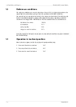
Page 208: ...ficiency and data analytics Wärtsilä maximises the environmental and economic performance of the vessels and power plants of its customers Wärtsilä is listed on the NASDAQ OMX Helsinki Finland See also www wartsila com WÄRTSILÄ is a registered trademark 2019 Wärtsilä Corporation Find contact information for all Wärtsilä offices worldwide www wartsila com contact ...

Reviews: