60 µm (mesh size)
Fineness (absolute) max.
Maximum permitted pressure drop at 50 cSt:
30 kPa (0.3 bar )
- clean filter
80 kPa (0.8 bar)
- alarm
7.3.8
Automatic filter, backflush flow (2F13)
When on-engine filter, It is recommended to select an automatic filter with an insert filter in
the backflushing line, thus enabling easy changeover to the insert filter during maintenance
of the automatic filter. Clean oil from backflush filter can go directly to oil tank. Some backflush
filter models operates properly when they have a moderate counterpressure at clean oil
discharge, thus these models have a simple pressure regulating valve afterwards.
Backflush filter sludge oil must be discharged to sludge tank, when no further post-filtration
occurs. To be re-used, it must be filtered by a sludge cartridge filter before it is conducted
back to the system oil tank. The sludge cartridge filter can be either integrated in the automatic
filter or separate. A bypass line discharging the oil from on-engine filter directly to tank
allowsbackflush filter maintenance, which should be bypassed for less time as possible.
Design data:
50 cSt (SAE 40, VI 95, appox. 63°C)
Oil viscosity
17 m3/h for Line engines, 25 m3/h for Vee engines
Design flow
100 °C
Design temperature
1.0 MPa (10 bar)
Design pressure
Fineness (absolute) max.
34 µm (mesh size), corresponding to approx 50 µm absolute
- automatic filter
50 µm (absolute
- sludge cartridge filter
Maximum permitted pressure drop at 50 cSt:
30 kPa (0.3 bar )
- clean filter
80 kPa (0.8 bar)
- alarm
7.4
Crankcase ventilation system
The purpose of the crankcase ventilation is to evacuate gases from the crankcase in order to
keep the pressure in the crankcase within acceptable limits.
Each engine must have its own vent pipe into open air. The crankcase ventilation pipes may
not be combined with other ventilation pipes, e.g. vent pipes from the system oil tank.
The diameter of the pipe shall be large enough to avoid excessive back pressure. Other possible
equipment in the piping must also be designed and dimensioned to avoid excessive flow
resistance.
A condensate trap must be fitted on the vent pipe near the engine.
The connection between engine and pipe is to be flexible. It is very important that the crankcase
ventilation pipe is properly fixed to a support rigid in all directions directly after the flexible
hose from crankcase ventilation outlet, extra mass on the oil mist detector must be avoided.
There should be a fixing point on both sides of the pipe at the support. Absolutely rigid mounting
between the pipe and the support is recommended. The supporting must allow thermal
expansion and ship’s structural deflections.
DAAB605814
7-15
7. Lubricating Oil System
Wärtsilä 46F Product Guide
Summary of Contents for 46F Series
Page 1: ...Wärtsilä 46F PRODUCT GUIDE ...
Page 4: ...This page intentionally left blank ...
Page 8: ...This page intentionally left blank ...
Page 18: ...This page intentionally left blank ...
Page 86: ...This page intentionally left blank ...
Page 104: ...This page intentionally left blank ...
Page 154: ...This page intentionally left blank ...
Page 162: ...This page intentionally left blank ...
Page 170: ...This page intentionally left blank ...
Page 176: ...This page intentionally left blank ...
Page 194: ...This page intentionally left blank ...
Page 200: ...This page intentionally left blank ...
Page 202: ...This page intentionally left blank ...
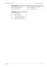
Page 207: ...Fig 21 7 List of symbols DAAF406507 7 DAAB605814 21 5 21 ANNEX Wärtsilä 46F Product Guide ...

