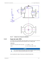
The expansion tank should be equipped with an inspection hatch, a level gauge, a low level
alarm and necessary means for dosing of cooling water additives.
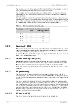
The vent pipes should enter the tank below the water level. The vent pipes must be drawn
separately to the tank (see air venting) and the pipes should be provided with labels at the
expansion tank.
The balance pipe down from the expansion tank must be dimensioned for a flow velocity not
exceeding 1.0...1.5 m/s in order to ensure the required pressure at the pump inlet with engines
running. The flow through the pipe depends on the number of vent pipes to the tank and the
size of the orifices in the vent pipes. The table below can be used for guidance.
Table 9-1
Minimum diameter of balance pipe
Max. number of vent
pipes with ø 5 mm ori-
fice
Max. flow velocity
(m/s)
Nominal pipe size
6
1.2
DN 40
10
1.3
DN 50
17
1.4
DN 65
28
1.5
DN 80
9.3.10
Drain tank (4T04)
It is recommended to collect the cooling water with additives in a drain tank, when the system
has to be drained for maintenance work. A pump should be provided so that the cooling water
can be pumped back into the system and reused.
Concerning the water volume in the engine, see chapter Technical data. The water volume in
the LT circuit of the engine is small.
9.3.11
Additive dosing tank (4T03)
It is also recommended to provide a separate additive dosing tank, especially when water
treatment products are added in solid form. The design must be such that the major part of
the water flow is circulating through the engine when treatment products are added.
The tank should be connected to the HT cooling water circuit as shown in the example system
diagrams.
9.3.12
HT preheating
The cooling water circulating through the cylinders must be preheated to at least 60 ºC,
preferably 70 ºC. This is an absolute requirement for installations that are designed to operate
on heavy fuel, but strongly recommended also for engines that operate exclusively on marine
diesel fuel.
The energy required for preheating of the HT cooling water can be supplied by a separate
source or by a running engine, often a combination of both. In all cases a separate circulating
pump must be used. It is common to use the heat from running auxiliary engines for preheating
of main engines. In installations with several main engines the capacity of the separate heat
source can be dimensioned for preheating of two engines, provided that this is acceptable
for the operation of the ship. If the cooling water circuits are separated from each other, the
energy is transferred over a heat exchanger.
9.3.12.1
HT heater (4E05)
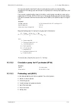
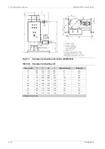
The energy source of the heater can be electric power, steam or thermal oil.
9-18
DAAB605814
Wärtsilä 46F Product Guide
9. Cooling Water System
Summary of Contents for 46F Series
Page 1: ...Wärtsilä 46F PRODUCT GUIDE ...
Page 4: ...This page intentionally left blank ...
Page 8: ...This page intentionally left blank ...
Page 18: ...This page intentionally left blank ...
Page 86: ...This page intentionally left blank ...
Page 104: ...This page intentionally left blank ...
Page 154: ...This page intentionally left blank ...
Page 162: ...This page intentionally left blank ...
Page 170: ...This page intentionally left blank ...
Page 176: ...This page intentionally left blank ...
Page 194: ...This page intentionally left blank ...
Page 200: ...This page intentionally left blank ...
Page 202: ...This page intentionally left blank ...
Page 207: ...Fig 21 7 List of symbols DAAF406507 7 DAAB605814 21 5 21 ANNEX Wärtsilä 46F Product Guide ...

