background image

61

Gear shift system

 noTiCe

Damage to the gear hub system caused by improper use.

Risk of damage!

•  When shifting gears, do not pedal hard.
•  When shifting gears, do not pedal backwards.
•  Shift down the gears in a timely fashion before ascents.

• 

If you are unsure about using the gear hub, ask your specialist 

dealer to explain how to correctly use the gear hub.

• 

Find out which gear hub system your bicycle is fitted with.

note:

 Depending on the bicycle model, your bicycle is equipped 

with a gear hub with or without a coaster brake (see Chapter 

“Bicy-

cle passport” on page 117

).

7.2.2.1 

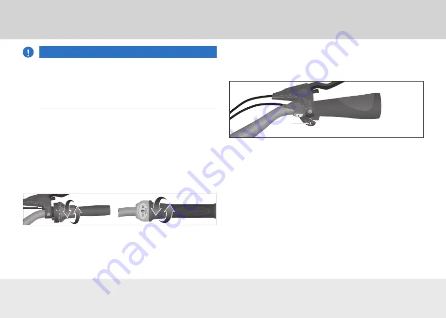
Changing gears with a twist-grip shifter

To change gears, turn the twist-grip shifter (see Fig. 

“Twist-grip 

shifter for gear hubs”

).

Fig.: Twist-grip shifter for gear hubs (example)

7.2.2.2 

Changing gears with a gear lever

Depending on the type of gear hub installed, the front gear lever 
will have two settings. The rear gear lever can either be pressed 
or pulled.

Fig.: Gear lever (example)

1  Gear lever

1

• 

To let the gear lever which has been pressed automatically 
return to its original position, release the gear lever after shift-
ing.

• 

To change down a gear, squeeze the gear lever that is furthest 

forward with your thumb until it engages for the first time (see 
Fig. 

“Gear lever”

).

In order to change up a gear, press or pull on the rearmost gear 

lever with your index finger.

Summary of Contents for Din en 82079-1

Page 1: ...Sales Hermann Hartje KG Tel 04251 811 90 info hartje de www hartje de uSeR ManuaL CoVeRinG oPeRaTion SeTTinGS MainTenanCe anD SeRViCinG Din en iSo 4210 Din en 82079 1 TReKKinG BiKe CiTY BiKe aTB uRBan...

Page 2: ......

Page 3: ...product defects are resolved by replacement or repair at no charge Guarantee repair services may be carried out only by a bicycle dealer specified by us The guarantee is only valid for the first owner...

Page 4: ...chapters Frame 1 Head tube 2 Top tube 3 Down tube 4 Rear frame chain stay 5 Rear frame seat stay 6 Seat tube 1 2 4 6 5 3 Pedal Saddle Seat post Pannier rack Reflector rear light Rear brake Axle nut Pr...

Page 5: ...6 1 Travelling with children in a child seat 17 3 6 2 Travelling with children in a children s trailer 18 4 Basic information 19 4 1 Symbols and terms 19 4 1 1 Symbols 19 4 1 2 Terms 19 4 1 3 Written...

Page 6: ...ic information 43 5 6 2 Operation 43 5 6 3 Settings 43 5 7 Coaster brake 44 5 7 1 Basic information 44 5 7 2 Operation 45 5 7 3 Settings 45 6 Lights 46 6 1 Basic information 46 6 2 Operation 47 6 2 1...

Page 7: ...information 68 8 2 2 Operation 69 8 2 3 Settings 69 8 3 Belt drive system 69 8 3 1 Basic information 69 8 3 2 Operation 70 8 3 3 Settings 70 9 Tightening the chain 72 9 1 Basic information 72 9 2 Sett...

Page 8: ...11 2 1 Setting the handlebar height 84 11 2 2 Handlebar direction 85 11 2 3 Handlebar position 85 11 2 4 Transport position 86 11 2 5 Riding position 86 12 Other components 88 12 1 Handlebars 88 12 1...

Page 9: ...108 13 1 Wheels 108 13 1 1 Basic information 108 13 1 2 Settings 109 13 2 Tyres and valves 109 13 2 1 Basic information 109 13 2 2 Settings 112 14 Storage and disposal 113 14 1 Storage 113 14 2 Dispos...

Page 10: ...Bicycles or e bikes that are not approved for road usage under German Road Traffic Licensing Regu lations are labelled accordingly on the seat tube or down tube see Fig Road Traffic Licensing Regulat...

Page 11: ...signates hazard with a low degree of risk which may result in minor or moderate injury if unheeded noTiCe This key word warns of possible damage to property 3 2 Proper use WaRninG Danger for children...

Page 12: ...s moving parts Risk of injury Wear tight fitting clothing on the legs Ensure no loose straps are hanging down e g shoe laces or jacket belts CauTion Slipping due to improper footwear Risk of injury W...

Page 13: ...to the public The bicycle is not intended to be subjected to above average strain during use e g the use of the bicycle in racing or competitive events is not considered to be in accordance with its i...

Page 14: ...ntly in force Ride in such a way that nobody suffers injury is endangered incapacitated or disturbed Use the cycle routes intended for bicycles according to reg ulations 3 3 1 Bicycle helmet For your...

Page 15: ...bicycles The triathlon gear levers are often on the handlebars The brake levers are at the ends of the standard handlebars When the bicy cle is ridden in an aerodynamic position the brake levers are...

Page 16: ...y e g the brakes After a fall or accident ask your specialist dealer to thoroughly check your bicycle for damage 3 6 Carrying children WaRninG Changed riding characteristics due to additional weight R...

Page 17: ...should only allow a child to ride in the child seat or child trailer if the child is wearing a suitable bicycle helmet which has been tested according to the relevant norms and bears the CE seal of co...

Page 18: ...with the trailer system attached Transport a maximum of two children in the child trailer Only use trailers with functional lighting equipment that com plies with the regulations applicable in your r...

Page 19: ...stays The rear wheel s axle is tightly screwed into the dropout Brake arm Contrary to the norm the lever installed on the chain stays as a bracket for the coaster brake is described as the brake arm...

Page 20: ...l fatigue caused by incorrect tightening of screw connections Risk of accident and injury Do not use the bicycle if you notice any loose screw connections Screw connections must be properly tightened...

Page 21: ...bar due to an incorrect sitting position Risk of accident and injury Ask your specialist dealer to adjust your sitting position correctly The optimal sitting position depends on the frame size of the...

Page 22: ...aterial fatigue or loose screw connections Risk of accident and injury Check the condition of your bicycle regularly Do not use the bicycle if you notice excessive wear or loose screw connections Do n...

Page 23: ...ot allow carbon components to come into contact with grease and oil 4 7 Protection against theft Protect your bicycle against theft For models with a frame lock If you are not able to keep watch over...

Page 24: ...nce on the braking performance it must be 100 added to the total weight note Particular caution must be taken with child trailers in com bination with e bikes due to the high speed and longer braking...

Page 25: ...re each ride following the inspection instructions If in any doubt ask your specialist dealer to show you how to check your bicycle Only use the bicycle if no damage is visible Only use the bicycle if...

Page 26: ...stem Check that the gear shift system works properly the tensioning devices Check the preload tension of all tensioning devices Check that all tensioning devices are positioned correctly the frame for...

Page 27: ...compo nent s rigidity can weaken Ask your specialist dealer to replace carbon components after a fall or accident After minor falls check all components of the bicycle e g if the bicycle has fallen ov...

Page 28: ...mild soapy solution to dampen the sponge After cleaning wipe dry all surfaces and components Maintain lacquered surfaces and metallic surfaces on the frame at least once every six months If your bicyc...

Page 29: ...tion in order to avoid blocking the wheels Always brake with both brakes simultaneously so as to achieve optimum braking efficiency WaRninG Blocking the read wheel can cause accidents Risk of accident...

Page 30: ...pen connections can cause hydraulic brakes to fail Risk of accident and injury Do not use the bicycle if you notice damage or leakages on the hydraulic cables or connections Ask your specialist dealer...

Page 31: ...when the brake lever is fully deployed If the clearance is less than 1 cm you should ask your spe cialist dealer to adjust the brake system 4 Check the brake pads for wear and tear If in any doubt ask...

Page 32: ...Brake lever for the front brake 2 Brake lever for the rear brake 2 1 5 3 Parking brake Aparking brake is a device that allows you to park your bicycle and prevent it from unintentionally rolling away...

Page 33: ...aulic rim brakes the brake fluid can also become damaged through use Please follow the instructions listed below for the front and rear brakes Remove dirt from the components of the rim brakes and the...

Page 34: ...heck for unusual noises when operating the rim brake If you hear unusual noises you should ask your specialist dealer to inspect the brake system Fig Mechanical rim brakes 1 Brake cable 2 Brake arm 3...

Page 35: ...mage and heavy soiling visual check Clean the brake pads if they are heavily soiled If the brake pads are damaged you should get them replaced by your specialist dealer Check that the brake shoes are...

Page 36: ...g distance also adjusts the tension of the brake cable 1 Screw in the adjusting screw until you are able to operate the brake lever safely see Fig Adjusting the brake lever Fig Adjusting the brake lev...

Page 37: ...ist dealer to inspect the brake system 4 Check whether you can only pull the brake lever towards the grip handle in such a way that the clearance between the brake lever and the grip handle is at leas...

Page 38: ...akes with new brake pads can cause the brake pads to vitrify Risk of damage Break in new discs away from road traffic 5 5 1 Basic information When the brake lever is operated the brake pistons within...

Page 39: ...air the brakes If the disc brakes are new or if the brake pads or the brake discs have been replaced the disc brakes will need to be broken in see Chapter Braking with disc brakes on page 41 5 5 2 ope...

Page 40: ...e g brake failure Risk of accident and injury Only use original brake pads for hydraulic disc brakes Seek professional advice when purchasing brake pads If you are unable to replace the brake pads cor...

Page 41: ...been replaced the disc brakes will need to be broken in Practise using the disc brakes before using them in road traffic To do so follow the manufacturer s information or ask your specialist dealer fo...

Page 42: ...intaining braking force Diminished brake action in disc brakes due to the brake system overheating is known as fading When the temperature at the point of contact between the brake pads and brake disc...

Page 43: ...s drag when the adjusting screw is screwed in to its maximum depth the brakes must be fully adjusted by your specialist dealer before the brake cable can be correctly set up 1 Unscrew the counternut b...

Page 44: ...1 Basic information When the coaster brake is operated a metallic ring inside the rear wheel hub is pressed against the outer hub shell causing the wheel to slow down Due to the bicycle s constructio...

Page 45: ...sk of accident and injury Adjustments to the coaster brake system should only be carried out by your specialist dealer If necessary you can ask your specialist dealer to show you how to adjust your co...

Page 46: ...ps a white reflector at the front and two red reflectors at the back see Fig Lighting equipment The light components must corre spond to the requirements of your respective country The front and rear...

Page 47: ...ither on the head tube above the mudguard or on the fork The rear light is switched on together with the headlight in all bicycle mod els Depending on the bicycle model the rear light is either fitted...

Page 48: ...tation you should stop riding 2 Make sure you remove snow and ice from your tyres and from the sidewall dynamo To switch the lights on press down on the sidewall dynamo from above see Fig On off switc...

Page 49: ...racket unscrew screw 1 anti clockwise until the bracket is loose enough to be turned see Fig Adjusting screws 3 Turn the bracket so it is vertically aligned with the head tube when viewed from the fro...

Page 50: ...te If the battery only has 20 charge left a red signal LED will light up in the centre of the rear light or the headlight respectively see Fig Detachable lights To ensure that the lights do not fail w...

Page 51: ...er of the micro USB socket see Fig USB socket 3 Insert the micro USB plug into the micro USB socket of the rear light and or headlight Fig Headlight example 1 Lever 2 Mounting connection 1 2 Fig USB s...

Page 52: ...apter Settings on page 49 Fig Headlight bracket example 1 Tab 2 Bracket 3 Handlebars 4 Belt 1 2 3 4 6 4 3 2 Rear light 1 Remove the rear light from its bracket 2 Position the bracket against the seat...

Page 53: ...unts of wear and tear The gear cables can become stretched through use In order to avoid premature wear and tear Pedal slowly and without applying force when changing gears Shift down the gears in a t...

Page 54: ...ring the higher the pedalling frequency The larger the chainring the lower the pedalling frequency Use the small chain ring for ascents Use the large chainring for sport riding Use a damp cloth to cle...

Page 55: ...inations cause the chain to skew leading to increased wear to chain rings sprockets and the chain Use the gear combinations in such a way that the chain remains parallel to the direction you are ridin...

Page 56: ...efore ascents If you are unsure about using the derailleur gears ask your specialist dealer to explain how to correctly use the derailleur gears Use the gear combinations in such a way that the chain...

Page 57: ...t side of the handlebars see Fig Gear lever To select a smaller chainring for ascending stretches of road press down or pull the rear gear lever on the left hand side of the handlebar 7 1 2 3 Gear con...

Page 58: ...for derailleur gears Fig Twist grip shifter for derailleur gears example 7 1 3 Settings noTiCe Damage to the gear shift system caused by incorrect set tings Risk of damage Consult your specialist dea...

Page 59: ...continue turning the ten sioning screw very gradually in the same direction until no more noises are heard while riding If this causes an increase in noises turn the tensioning screw very gradually in...

Page 60: ...r cable casing or torn wires visual check 4 Hang your bicycle from its frame 5 Turn the pedal crank 6 Shift through all the gears 7 Check to see if all gears shift into place correctly and that no unu...

Page 61: ...2 2 1 Changing gears with a twist grip shifter To change gears turn the twist grip shifter see Fig Twist grip shifter for gear hubs Fig Twist grip shifter for gear hubs example 7 2 2 2 Changing gears...

Page 62: ...tment process if both markings are not aligned on the rear wheel hub 6 Tighten the counter nut Carefully tighten the counter nut Fig Nexus settings 1 Knurled nut 2 Counter nut 3 Marking 4 Fixing screw...

Page 63: ...ar and switch to the 4th gear see Fig Twist grip shifter for gear hubs Use as little force as possible when setting the gears to prevent over shifting The cable adjustment screw can be found underneat...

Page 64: ...e adjustment screw can be found underneath the han dlebar 2 Move the cable adjustment screw on the twist grip shifter in such a way that both markings are aligned on the rear wheel hub see Fig Marking...

Page 65: ...hift down the gears in a timely fashion before ascents 7 3 1 Basic information The rear wheel is fitted with a continuously variable gear shift sys tem By turning the twist grip shifter the gear shift...

Page 66: ...re is less than 0 5 mm of clearance available screw the adjustment nut clockwise see Fig Enviolo settings 2 If there is more than 1 5 mm of clearance available unscrew the adjustment nut anticlockwise...

Page 67: ...stem see Fig Chain drive system and Fig Belt drive system 8 1 Pedal drive 8 1 1 Basic information Assembly consisting of pedal pedal crank bottom bracket and chainring Fig Pedal drive 1 Chainring 2 Bo...

Page 68: ...bike dealer 8 2 Chain drive system 8 2 1 Basic information Fig Chain drive system 1 Sprocket 2 Chainring 3 Chain 1 2 3 Achain drive system is compatible with gear hubs coaster brakes and derailleur ge...

Page 69: ...cket or chainring have become sharp or pointed you should replace the sprocket or chainring Fig Sprocket 1 Damage to the chainring 2 Damage to the sprocket 1 2 8 3 Belt drive system 8 3 1 Basic inform...

Page 70: ...ls with your feet in order to set the belt drive and thus the whole bicycle in motion 8 3 3 Settings 8 3 3 1 Checking the belt tension noTiCe Damage to the belt due to incorrect tool Risk of damage Th...

Page 71: ...Wear 1 Damage to the belt 2 Damage to the sprocket 1 2 Check the belt drive system regularly for signs of wear If you notice damage e g sharp teeth cracks or missing teeth you should replace the belt...

Page 72: ...g Eccentric chain ten sioner A and Eccentric chain tensioner B to see which type your bicycle is fitted with If you do not have the necessary expertise or correct tools to adjust the chain using the e...

Page 73: ...er on the dropout see Fig Chain tensioner on the dropout If you lack the necessary expertise or correct tools to adjust the chain using the chain tensioner on the dropout have your special ist dealer...

Page 74: ...rear wheel is positioned in line with the frame 7 If the rear wheel is not positioned in line with the frame tighten the adjusting screw on the side turned away from the chain by one full turn If this...

Page 75: ...e clamping device and the folding hinges Do not reach behind the clamping lever when closing the clamping devices Wear protective gloves if necessary This set of folding instructions presumes that you...

Page 76: ...r has locked into place and that you can no longer fold or unfold the pedals Fig Folding pedal 1 Slider 1 10 2 Clamping lever on the handlebar 10 2 1 Basic information The clamping lever on the handle...

Page 77: ...ls to adjust the clamping lever have your specialist dealer adjust it for you 1 Open the clamping lever 2 Turn the adjusting screw inwards one quarter of a turn 3 Close the clamping lever and check th...

Page 78: ...the fastener lock into place see Fig Locking the head tube 4 Check whether the fastener is locked properly by pulling on the clamping lever If you cannot lock the fastener properly ask your specialist...

Page 79: ...to the saddle when opening the clamping lever Turn the clamping lever outwards see Fig Seat post clamp To fold the folding bicycle push the saddle downwards To use the folding bicycle adjust the heigh...

Page 80: ...ock the fastener on the folding hinge 10 5 2 operation 10 5 2 1 opening the folding hinge on the frame 1 Push the locking mechanism in the direction of travel 2 Turn the clamping lever outwards see Fi...

Page 81: ...th caution Observe the moving parts when collapsing the folding bicycle Wear protective gloves noTiCe Brake and gear cables can be bent or crushed between the moving parts of the folding bicycle Risk...

Page 82: ..._Adapter back 1 2 10 7 unfolding the folding bicycle WaRninG If the folding bicycle is improperly unfolded it may snap closed again while it is being ridden Risk of accident and injury Check whether a...

Page 83: ...ge 78 5 Rotate the handlebar until the brake lever and other compo nents of the handlebar can be easily reached 6 Close the clamping lever on the handlebar see Chapter Closing the clamping lever on th...

Page 84: ...r the handlebars Adjust the handlebar height so that you can sit in a comfort able sitting position and can easily operate all components located on the handlebars while riding Fig Operating elements...

Page 85: ...sition Fig Handlebar position 1 Handlebar clamp 2 Clamp screw 3 Calibration 20 10 0 10 20 20 10 0 10 20 2 1 3 0 0 note Adjusting the handlebar position requires simultaneous adjustment of the hand bra...

Page 86: ...ick release lever outwards see Fig Transport position 2 Lower the steering wheel completely 3 Pull the latch upwards 4 Carefully rotate the handlebar 90 against the front wheel until the latch self en...

Page 87: ...heel until the latch self engages You may need to hold the front wheel firmly to do this Fig Riding position 13 12 11 10 0 1 2 3 4 Close the quick release by turning the quick release lever inwards un...

Page 88: ...fitted with either a threadless handlebar stem or a quill stem Check to find out which type of handlebar stem your bicycle is fitted with see Fig Handlebar stems Certain models are fitted with an ang...

Page 89: ...andlebar stem 1 Pull the cap on the top of the quill stem upwards see Fig Handlebar stems right 2 Unscrew the internal screw with 1 to 2 turns in an anti clock wise direction 3 Take hold of the handle...

Page 90: ...ise until you can turn the handlebars away from the front wheel see Fig Head tube note The following step describes how to adjust the head bearing Fig Head tube 1 Screws 2 Cap 3 Threadless handlebar s...

Page 91: ...ed spanners or two headset spanners the spanner size may vary between individual bicycle models 1 Place the bicycle in an upright position 2 Loosen the clamping nuts 3 Tighten the bearing until there...

Page 92: ...of the saddle and seat post together Never overload either the saddle or the seat post if you are not sure about the permissible load for the saddle and or seat post ask your specialist dealer The sa...

Page 93: ...the button is depressed pull the saddle up or push it down as needed 3 Release the button 4 If the range of movement is not sufficient for the required adjustment you can adjust the seat post to alter...

Page 94: ...seat post or tighten the screw on the seat post clamp clockwise taking the torques into account 6 Check that the seat post is securely tightened To do this sit on the saddle and rock backwards and for...

Page 95: ...e have it adjusted by your specialist dealer 12 3 Pannier rack 12 3 1 Basic information The pannier rack is a device on the bicycle that enables the rider to carry luggage Depending on the bicycle mod...

Page 96: ...s to transport your luggage WaRninG Changed riding characteristics due to additional weight Risk of accident and injury Familiarise yourself with how it feels to ride your bicycle with additional lugg...

Page 97: ...ourself with how it feels to ride your bicycle with additional attachments such as saddle bags and front baskets before riding on the road Saddle bags front baskets and lowriders dramat ically impair...

Page 98: ...bell is a metal bell on your bicycle with a clear ringing sound You can attract the attention of other road users by ringing the bell If you do not hear a clear high ringing sound when attempting to...

Page 99: ...ely position your bicycle using the stand you should adjust the stand so it can be properly used If you are unable to adjust the stand have it adjusted by your specialist dealer 12 7 Frame lock note T...

Page 100: ...ycle may be fitted with quick release on the wheel axles or on the seat post clamp Use Fig Quick release to check if your bicycle is fitted with a quick release 1 Open and close the quick release leve...

Page 101: ...crew or axle nut clockwise one quar ter of a turn see Fig Adjusting the quick release mechanism 3 Close the quick release and check the seat post wheel is securely tightened 4 Repeat the process until...

Page 102: ...rmitted to disas semble and repair your suspension seat post suspen sion fork and rear frame suspension noTiCe Impact noises occur if suspension is set up incorrectly Risk of damage If you feel hard s...

Page 103: ...y when the bicycle features several different suspension elements note To ensure optimally adjusted sag your specialist dealer may install stiffer or softer springs in the suspension 12 9 1 3 Lock out...

Page 104: ...unlock the suspension fork turn the control knob 90 anti clockwise or press the unlock button note Even when locked the suspension system still provides cushioning on uneven surfaces of up to 15 mm 1...

Page 105: ...bout per missible air pressure levels 12 9 1 9 Suspension fork travel To reduce suspension travel distance 1 Push the button labelled Push and hold it down see Fig Suspension travel 2 Press down on th...

Page 106: ...and out Afterwards wipe up any excess lubricant with a clean cloth Compress the suspension seat post in and out and check for noises If you hear unusual sounds when compressing and decom pressing or...

Page 107: ...w for the suspension seat post on the seat post clamp anti clockwise until the suspension seat post can be shifted up or down or open the quick release by turning the quick release lever outwards 2 Pu...

Page 108: ...yre does not have an inner tube road bikes are fitted with so called tubular tyres or mountain bikes are fitted with UST tyres Universal System for Tubeless The wheels are exposed to considerable stre...

Page 109: ...that the tension is equal on all spokes If the tension varies or if spokes are loose ask your special ist dealer to tauten the spokes Alternatively you can stroke a wooden or plastic baton over the sp...

Page 110: ...that the tyre is 52 mm wide when fully inflated and has an inner diameter of 559 mm Size in inches If the tyre is described as 26 2 35 this means that the tyre is 2 35 wide when fully inflated and ha...

Page 111: ...h a pressure gauge Observe the maximum tyre pressure which is indicated by the lower value printed on the rim or on the side of the tyre Tyre inflation pressure is indicated in psi pound per square in...

Page 112: ...ump with a pressure indicator to the valve and read the pressure values Ensure that you are using the correct attachment for your type of valve If the air pressure is too low pump the tyres with an ai...

Page 113: ...page 55 WaRninG Danger for children or for individuals with insufficient knowledge or abilities Risk of accident and injury Do not allow children to play with the bicycle Do not allow children to clea...

Page 114: ...l leaflets about cleaning individual components 14 2 Disposal If you own an e bike you should also read the original user manual for information about disposal 14 2 1 Disposing of the packaging Sort t...

Page 115: ...nspection After approximately 200 km or 2 months Work done Materials installed Second inspection After approximately 1000 km or 1 year Work done Materials installed Third inspection After approximatel...

Page 116: ...After approximately 3000 km or 3 years Work done Materials installed Fifth inspection After approximately 4000 km or 4 years Work done Materials installed Sixth inspection After approximately 5000 km...

Page 117: ...k Brake Front brake Rim brake Roller brake Disc brakes Rear brake Rim brake Roller brake Disc brakes Coaster brake Wheels Rim size 20 24 26 27 5 28 29 Tyre size Rim Wear limit Available Tensioning dev...

Page 118: ...ts Child seat Available Can be fitted Not suitable for child seats Frame lock Available Trailer Installing a trailer coupling to the saddle clamp is not allowed Permissible total weight 130 kg 140 kg...

Page 119: ...stomer had been briefed on how to use the bicycle the customer had been informed that an inspection must be carried out after the first 200 km and the customer had been asked to read the user manual b...

Page 120: ...ol GmbH Schleidenstra e 1 22083 Hamburg Tel 49 0 40 600 202 0 www hermesworld com This user manual for your bicycle fulfils the requirements and the domain of validity of the DIN EN 4210 and DIN EN 82...

Page 121: ...Sales Hermann Hartje KG Tel 04251 811 90 info hartje de www hartje de Presented by...

Reviews: