43
Brakes
5.6
Roller brakes
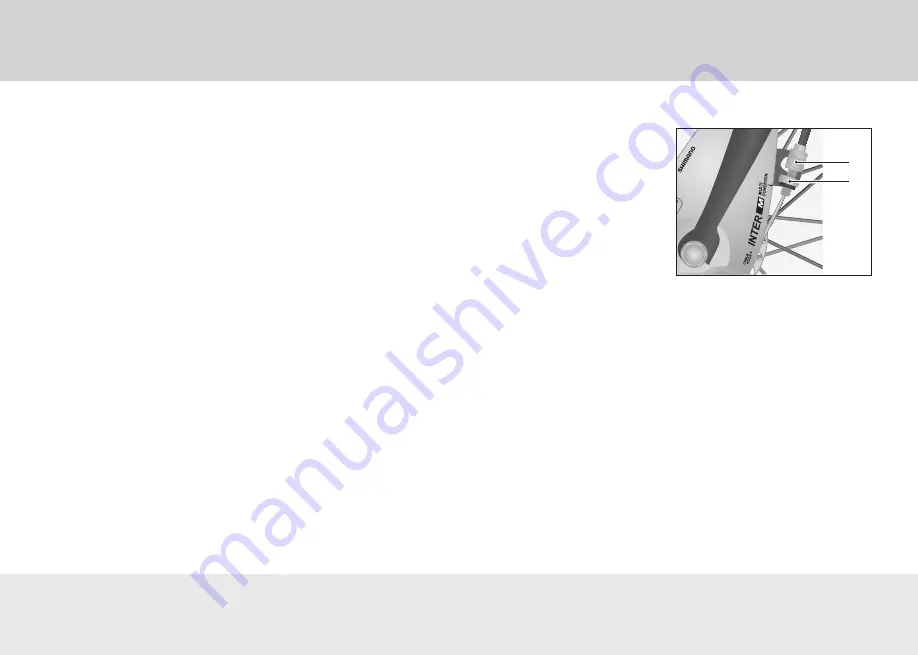
The roller brake is mounted in the front or rear wheel hub (see
Fig.
“Roller brakes”
). When the brake is operated, rollers inside
the front or rear wheel hub are pressed against the hub casing.
5.6.1
Basic information
The use of roller brakes can cause wear and tear to the brake
cables, the brake rollers and the hub casing.
5.6.2
operation
When an even braking power is exerted, the rear wheel will lock
more readily than the front wheel.
Depending on the bicycle model, your bicycle may be fitted with
different types of brakes on the front and rear wheels.
•
To operate the brakes, pull the brake lever towards the han-
dlebars using your fingers
(see Chapter
“Brakes” on page 29
).
•
Regulate the brake action using the force you apply when pull-
ing the brake lever.
To release the brakes, let go of the brake lever.
To ensure a short braking distance, you should brake using both
brakes at the same time.
5.6.3
Settings
note:
If the roller brakes drag when the adjusting screw is screwed
in to its maximum depth, the brakes must be fully adjusted by your
specialist dealer before the brake cable can be correctly set up.
1.
Unscrew the counternut by turning it once or twice in an anti-
clockwise direction (see Fig.
“Roller brakes”
).
2.
Unscrew the adjusting screw until the brakes start to drag
without the brake lever being operated.
As you do this, take hold of the
brake cable and gently pull on it
until the adjusting screw can be
turned more easily.
•
Unscrew the adjusting
screw by a maximum of
5 rotations.
• Turn the front/rear wheel
to check if the brakes are
dragging.
3. Gradually tighten the adjust-
ing screw until the front/rear
wheel spins freely without
the brake lever being oper-
ated.
4.
Check whether you can only pull the brake lever towards the
grip handle in such a way that the clearance between the
brake lever and the grip handle is at least 1 cm.
•
If you cannot adjust the rollers brakes this way, have your
specialist dealer adjust the roller brake system for you.
5. Turn the counternut in a clockwise direction and tighten it
carefully.
Fig.: Roller brakes
1 Adjusting screw
2 Counter nut
1
2


