background image

50            Chapter 3    Web Page Of RDU-A G2 

RDU-A G2 Intelligent Monitoring Unit    User Manual 


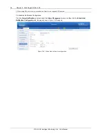
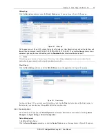
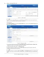
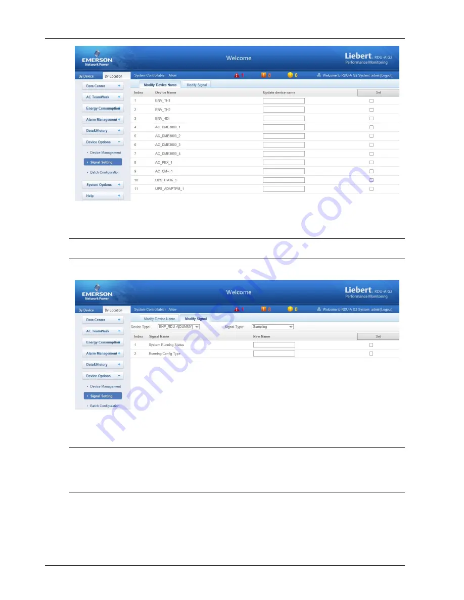
Figure 3-60    Modify device name 

On the page shown in Figure 3-60, you can modify the device name. Type the new device name and click the 

Set


button to make all setting effective. 


Note 

The characters of device name and signal name can be English letters, digits, space and underline, other characters are invalid. 


Click 

Modify Signal

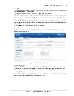
, the page shown in Figure 3-61 pops up. 


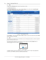
Figure 3-61    Modify signal 

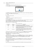
On the page shown in Figure 3-61, you can modify the signal name as well as the alarm level of the alarm signal. 

Choose 

Device Type

 and 

Signal Type

, type the new signal name, and click the 

Set

 button to make it effective. 


Note 

1. For Env TH and Env 4DI, the system has the linkage modifying function for the signal name, that is, when the sampling signal 
name is modified, the names of corresponding control signal, setting signal and alarm signal will be modified as well. Therefore, 
the page only supplies the function of modifying sampling signal name. 

2. The signal name modified here will be used as default signal name of the device. 


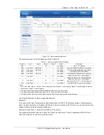
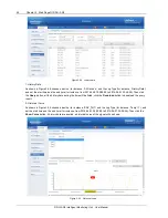
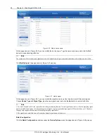
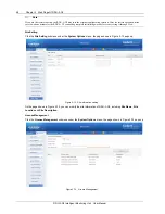
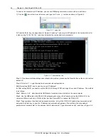
Batch Configuration 

Click the 

Batch Configuration

 submenu under the 

Device Options

 menu, the page shown in Figure 3-62 pops up. 

Summary of Contents for Liebert RDU-A-G2

Page 1: ...Liebert RDU A G2 User Manual ...

Page 2: ...sonnetworkpower com cn 客户服务热线 4008876510 E mail enpc service emerson com Emerson Network Power provides customers with technical support Users may contact the nearest Emerson local sales office or service center Copyright 2014 by Emerson Network Power Co Ltd All rights reserved The contents in this document are subject to change without notice Emerson Network Power Co Ltd Address No 1 Kefa Rd Scie...

Page 3: ......

Page 4: ...认证 7 第二章 硬件安装 8 2 1 安装准备 8 2 1 1 注意事项 8 2 1 2 环境要求 8 2 1 3 空间要求 8 2 1 4 安装工具 8 2 2 安装 RDU A G2 主机 9 2 2 1 机械安装 9 2 2 2 电气连接 9 2 3 安装扩展卡及传感器附件 10 2 3 1 安装扩展卡 10 2 3 2 安装智能传感器 10 2 3 3 安装物理传感器 11 第三章 RDU A G2 的 Web 界面 12 3 1 登录准备 12 3 1 1 检查 IP 地址连通性 12 3 1 2 检查浏览器版本 12 3 1 3 检查浏览器设置 12 3 2 登录 RDU A G2 16 3 2 1 授权开机 16 3 2 2 登录页面 16 3 2 3 取回密码 17 ...

Page 5: ...时链接 20 3 3 4 解除超时 20 3 3 5 注销登录 21 3 3 6 实时告警提醒设置 21 3 4 菜单项 21 3 4 1 机房信息 22 3 4 2 空调群控 25 3 4 3 能耗管理 29 3 4 4 告警管理 31 3 4 5 数据管理 38 3 4 6 配置管理 42 3 4 7 系统设置 47 3 4 8 帮助信息 59 第四章 维护 60 4 1 恢复默认设置 60 4 2 常见问题处理 60 附录一 缩略词 63 附录二 标准配置清单 64 附录三 有毒有害物质或元素标识表 65 ...

Page 6: ... RDU A G2 与 RDU A 的硬件功能差异见表 1 1 表1 1 RDU A G2 与 RDU A 硬件功能差异 功能差异 RDU A RDU A G2 电源输入 1 路外置电源 2 路内置电源 支持只接入 1 路和同时接入 2 路 扩展插槽 仅支持 1 个扩展插槽 并且只能接入 IRM 4COM 卡 支持 2 个扩展插槽 每个扩展槽都可插入 IRM 4COM 卡 IRM 8DIAI 卡 IRM 8DOAO 卡 网口 单网口且 IP 只能为手动设置 双网口且 IP 并支持 DHCP 动态获取 IRM 传感器接入 最大仅支持接入 28 个节点 28 个节点包含产品自带的 DOOR1 DOOR2 WATER SMOKE 口的节点设备 最大支持接入 32 个节点 USB 口 1 个 最大仅可接入 1 个 USB Modem 或摄像头 2 个 最大可支持接入 1 个 USB Modem 和...

Page 7: ...RDU A G2 电源 1 带电 熄灭 RDU A G2 电源 1 断电 Power2 绿色 点亮 RDU A G2 电源 2 带电 熄灭 RDU A G2 电源 2 断电 RDU A G2 主机前面板上有 3 个指示灯 位置如图 1 1 所示 其定义见表 1 4 表1 4 前面板指示灯定义 丝印 颜色 状态 描述 Power1 绿色 点亮 RDU A G2 电源 1 带电 熄灭 RDU A G2 电源 1 断电 Power2 绿色 点亮 RDU A G2 电源 2 带电 熄灭 RDU A G2 电源 2 断电 Run Alarm 绿色 红色 绿色 无告警 红色 告警 复位按钮 持续按下复位按钮 丝印为 Reset 4 秒 待运行 告警灯熄灭后松手 RDU A G2 将在系统重启后恢复 IP 地址及密码为 出厂默认值 默认值见表 1 6 调试口 RDU A G2 主机提供 1 路调试口 U...

Page 8: ... 表1 7 继电器输出口参数 继电器输出口 输出 范围 接口 用途 DO1 DO2 电压 11V 14V RJ45 1 DO 输出 可接入告警灯 2 两个端口最大总功率可支持 2 4W 3 支持短路保护功能 总电流 0 2A 数字量输入口 RDU A G2 主机提供 4 路数字量输入口 位置如图 1 1 所示 其参数见表 1 8 表1 8 数字量输入口电性能参数 丝印 定义 额定输出电压 输出电流 总 最大输出功率 总 端口过载保护 DI1 门磁 1 接口 12Vdc 0 2A 2 4W 支持过载保护 DI2 门磁 2 接口 Smoke1 烟雾接口 1 Smoke2 烟雾接口 2 传感器接口 RDU A G2 主机提供 2 路传感器接口 包含 4 个 RJ45 接口 位置如图 1 1 所示 其参数见表 1 9 表1 9 传感器接口电气参数 丝印 定义 额定输出电压 输出电流 总 最大输出功...

Page 9: ...图 1 2 所示 指示灯 Power COM5 串口 COM6 COM7 COM8 COM5 COM6 COM7 COM8 图1 2 IRM 4COM 卡 IRM 4COM 卡的指示灯定义见表 1 12 表1 12 IRM 4COM 卡指示灯定义 丝印 颜色 状态 描述 Power 绿色 点亮 IRM 4COM 板带电 熄灭 IRM 4COM 板掉电 COM5 COM8 黄色 闪烁 有数据收发 熄灭 无数据收发 IRM 8DIAI 卡 选配 IRM 8DIAI 卡提供 8 路数字量或模拟量输入接口 数字量和模拟量自适应 支持数字量 模拟量输入 其外观如图 1 3 所示 DI AI1 DI AI2 DI AI3 DI AI4 DI AI5 DI AI6 DI AI7 DI AI8 数字量 模拟量输入1 8 图1 3 IRM 8DIAI 卡 IRM 8DIAI 卡的接口定义见表 1 13 表1...

Page 10: ... AI_I 4 脱落检测 脱落检测 GND GND 脱落检测 脱落检测 5 GND GND GND GND 6 常开 DI NC RXD 常开 DI 7 COM D D COM 8 NC NC D D NC AI_V 注 1 RJ45 端口的线序排列为缺口向下 从左到右依次为 1 8 2 D D 为 RS485 差分信号的两种电平 3 NC Not Connected 1 3 主要功能 RDU A G2 的主要功能见表 1 16 表1 16 RDU A G2 主要功能 主要功能 说明 设备监控 实现对机房环境的视频监视和对不同智能设备的数据采集和处理 并且通过 Web 界面控制智能设备 空调群控 按照一定的规则 监控和调度参与群控的各台空调 以达到降低空调能耗 延长空调整体寿命 避免群组空 调间竞争运行的目的 能耗管理 支持功率模式和电能模式的 PUE 及系统负载百分比的统计 并能显示其实...

Page 11: ...统设置 监控单元 采集 RDU A G2 系统信息 网络设置 1 IP 子网掩码 网关 DNS 等相关网络信息设置 2 上层监控系统 RDU M 机房管理器访问 RDU A G2 的权限设置 3 远程服务设置 用户管理 增加 修改和删除用户信息 时间校准 校准 RDU A G2 实时时钟 恢复默认 重启 RDU A G2 和恢复默认配置 站点信息设置 在线修改站点信息 授权码管理 通过授权码完成 RDU A G2 功能和接入能力的扩展 系统升级 在线升级应用程序 标题栏设置 设置 Web 页面上方的标题和 Logo 图片 帮助信息 关于 RDU A G2 显示 RDU A G2 的产品序列号 特征码及版本信息 并提供用户手册及工具软件的下载 1 4 技术指标 1 4 1 环境指标 RDU A G2 的环境指标见表 1 17 表1 17 环境条件 项目 要求 使用场所 通常为数据中心或者计算...

Page 12: ...口接入节点 标准 4 类双绞线 100 4 3 DO 口接入节点 标准 4 类双绞线 100 2 4 通过串口组网支持的设备类型数量 11 5 通过网络 TCP IP SNMP 组网支持 的设备类型数量 16 6 支持接入智能设备数量 标准 4 类双绞线 串口 100 串口 32 7 注 1 温度 温湿度 门磁 水浸 4DI 自身 4DO 自身 DO 设备等每个传感器或设备按照 1 个节点计算 烟感和红外每个传感器 按照 4 个节点计算 只能接入组内地址为 1 设备 2 接入能力同 1 但只能接入组内地址为 2 的设备 3 DI 包括机身自带 DI1 DI2 Smoke1 Smoke2 四个接口 4 声光告警灯有两路接入点 DO1 DO2 两路接入点亦可作为两路开关量输出以做它用 5 通过串口组网 3 个默认串口 4 4COM 扩展卡 2 最大支持 11 种设备类型 6 通过网络组网 TC...

Page 13: ... 2 1 2 环境要求 运行环境 RDU A G2 必须安装在室内 具体要求参见表 1 17 防静电 为了将静电影响降到最低点 需要采取下列措施 机房内保持适当的温度和湿度 参见表 1 17 当人体接触电路板前 应佩戴防静电手腕 穿防静电工作服 如果在现场无防静电手腕和防静电工作服 则需用水将 手部冲洗干净 并擦干 抗干扰 为了抗干扰 需要采取下列措施 避免将 RDU A G2 工作地和电力设备的接地装置或防雷接地装置合用 两者尽可能远离 远离强功率无线电发射台 雷达发射台 高频大电流设备 必要时采取电磁屏蔽的方法 2 1 3 空间要求 将 RDU A G2 放置在远离热源的地方 建议将 RDU A G2 安装在 19 英寸标准机柜中 在设备周围 至少留有 10mm 的空间 确保有足够的散热空间 2 1 4 安装工具 安装工具见表 2 1 表2 1 安装工具 工具名称 规格型号 用途 螺丝...

Page 14: ...种安装方式 前端安装和后端安装 分 别如图 2 1 和图 2 2 所示 挂耳 2个 M4螺钉 6颗 图2 1 前端安装挂耳 挂耳 2个 M4螺钉 6颗 图2 2 后端安装挂耳 3 用 M6 浮动螺母将 RDU A G2 主机通过两侧的挂耳固定在机架上 2 2 2 电气连接 RDU A G2 主机电气连接步骤如下所示 1 根据供电端接口类型选择 C14 或国标线缆 RDU A G2 附件 取出对应的电源线 一端连接到 RDU A G2 主机的电 源输入接口 并将如图 2 3 所示的防脱扣卡上 防脱扣 电源线一端 图2 3 电源防脱扣示意图 2 确保连线正确后 电源线另外一端插头接入供电电源 注意 RDU A G2 主机提供双电源备份供电 可选择一路供电或两路供电 输入电压 100Vac 240Vac 频率 45Hz 66Hz ...

Page 15: ...将扩展卡插入 RDU A G2 对应扩展槽内 并拧紧两侧螺 钉 如图 2 4 所示 扩展卡 螺钉 图2 4 扩展卡安装示意图 2 3 2 安装智能传感器 智能传感器包括 IRM S01T 智能温度传感器 简称 IRM S01T IRM S02TH 智能温湿度传感器 简称 IRM S02TH IRM S04DI Phoenix 接口智能数字量输入传感器 简称 IRM S04DI 和 IRM S04DIF RJ45 接口智能数字量输入传感器 简 称 IRM S04DIF 其外观如图 2 5 所示 IRM S01T IRM S02TH IRM S04DI IRM S04DIF 图2 5 智能传感器 安装步骤 智能传感器的安装步骤参见对应智能传感器的用户手册 IRM S01T 参见 IRM S01T 智能温度传感器用户手册 IRM S02TH 参见 IRM S02TH 智能温湿度传感器用户手册 ...

Page 16: ...入传感器用户手册 2 3 3 安装物理传感器 物理传感器包括 烟雾传感器 水浸传感器 红外传感器和门磁传感器 烟雾 水浸 红外和门磁传感器有两种安装方式 直接接入 RDU A G2 后面板上的 DI 接口 丝印为 DI1 DI2 Smoke1 和 Smoke2 每个口可任意接入烟雾 水浸 红 外和门磁的一种 接线线序见表 1 15 通过 IRM S04DI 或 IRM S04DIF 接入 RDU A G2 将传感器接入 IRM S04DI 或 IRM S04DIF 的数字量输入口 接线线 序参见 IRM S04DI Phoenix 接口智能数字量输入传感器用户手册 或 IRM S04DIF RJ45 接口智能数字量输入传感 器用户手册 ...

Page 17: ...RDU A G2 页面功能的正常使用 请参照本节内容选择并设置浏览器选项 3 1 1 检查 IP 地址连通性 通过 Web 登录 RDU A G2 前请首先确认 RDU A G2 的 IP 地址 并测试其连通性 有关测试方法 参见 4 2 常见问题处 理一节中的问题 5 3 1 2 检查浏览器版本 建议使用的浏览器版本包括 IE10 或 IE11 3 1 3 检查浏览器设置 检查 IE 常规设置 双击 IE 图标运行该软件 点击菜单工具 Internet 选项 点击常规页签中的设置 S 将检查所存网页的较新版本选择 为每次访问网页时 E 检查 如图 3 1 所示 图3 1 常规设置 检查 IE 代理设置 1 双击 IE 图标运行该软件 点击菜单工具 Internet 选项 然后选择连接页签 弹出如图 3 2 所示页面 ...

Page 18: ...界面 13 RDU A G2 智能监控单元 用户手册 图3 2 选择连接页签 2 如图 3 2 所示的页面中 点击局域网设置 L 弹出如图 3 3 所示页面 图3 3 局域网设置 3 咨询您所在网络的网络管理员 询问其是否需要进行代理配置及配置方法 如果无需代理请不要勾选任何选项 检查 IE 安全设置 1 双击 IE 图标运行该软件 点击菜单工具 Internet 选项 然后选择安全页签 弹出如图 3 4 所示页面 图3 4 安全设置 1 ...

Page 19: ... 的 Web 界面 RDU A G2 智能监控单元 用户手册 2 如图 3 4 所示 选择受信任的站点 点击自定义级别 C 弹出如图 3 5 所示对话框 图3 5 安全设置 2 3 如图 3 5 所示 将重置自定义设置选为 中低 并点击重置 E 按钮结束重置自定义设置 4 如图 3 6 所示 设置启用文件下载 图3 6 启用文件下载 5 如图 3 7 所示 设置启用对未标记为可安全执行脚本的 ActiveX 控件初始化并执行脚本 ...

Page 20: ...第三章 RDU A G2 的 Web 界面 15 RDU A G2 智能监控单元 用户手册 图3 7 启用 ActiveX 控件 6 如图 3 8 所示 将 RDU A G2 的 IP 地址添加到可信站点的列表中 图3 8 添加可信站点 ...

Page 21: ...2 168 0 254 LAN2 默 认 IP 为 192 168 1 254 弹出授权开机页面 如图 3 9 所示 若未出现授权开机页面 参见 4 2 常见问题处理中的问题 5 进行处理 图3 9 授权开机页面 2 拨打艾默生网络能源客户服务电话 400 887 6510 提供特征码至客服人员 即可获取开机密码 3 在开机密码文本框里输入获得的开机密码 点击确定按钮 若开机密码正确 系统自动跳转到登录页面 见图 3 10 3 2 2 登录页面 1 启动 IE 在地址栏中输入 RDU A G2 的 IP 地址 出现登录页面 如图 3 10 所示 若未出现登录页面 参见 4 2 常 见问题处理中的问题 5 进行处理 清澈蓝 深海蓝 图3 10 RDU A G2 登录页面 ...

Page 22: ...3 2 3 取回密码 若忘记用户密码 可在登录页面 单击忘记密码按钮 屏幕显示取回密码页面 如图 3 11 所示 图3 11 取回密码页面 输入您的用户名 单击取回密码按钮 您的密码会发送到您之前设置的邮箱或手机 点击返回登录按钮取消操作 注意 1 您只有事先在短信模块和邮件服务器配置页面正确设置了邮件或短信参数 才能收到系统发出的密码 具体的设置 方法见 3 4 4 告警管理中的告警通知配置 2 取回的密码是系统随机产生的新密码 请成功登录后自行进行修改 3 3 RDU A G2 主页 RDU A G2 主页分为按设备浏览和按位置浏览 登录成功后 默认显示为按位置浏览 如图 3 12 所示 3 3 1 按位置浏览 如图 3 12 所示 点击菜单项上方按位置浏览选项卡 在右侧的显示区将显示按位置浏览页面 用户可以根据机房设备的 物理位置自定义显示一个平面布局图用于集中显示 经过简单的配置后...

Page 23: ...Web 界面 RDU A G2 智能监控单元 用户手册 1 2 3 4 6 5 7 8 9 10 11 1 菜单项 2 可控状态 3 各级别实时告警数目 4 系统标题 5 注销 当前用户 6 Logo 7 设置信号按钮 8 设备过滤选项 9 实时告警显示列表 10 告警提醒设置 11 校时链接 图3 12 RDU A G2 主页 按位置浏览 点击图 3 12 中设置信号按钮使主页进入设置状态 如图 3 13 所示 图3 13 设置页面 ...

Page 24: ...图片 图3 14 设置背景 注意 只允许上传 gif jpg 及 bmp 格式的图片 最大 500K 2 显示设置 点击显示设置按钮 弹出如图 3 15 所示页面 选择信号显示方式 鼠标悬浮 始终显示 选择设备图标是否显示 选择设备名称后 该设备的信号将显示在下方的方框内 用户可根据需要选择要显示的设备信号 但最大不超过 4 个 图3 15 显示设置 注意 1 信号显示方式和设备图标显示方式对当前所选设备有效 不同设备可单独设置不同的显示方式 2 设置温湿度和 DI 信号的显示方式时 选择 其他设备及传感器 进行统一设置 3 自定义设备位置 主页进入设置状态后 在主页上显示的设备 信号 图标可按住鼠标左键进行自由拖拽 4 重置 点击重置按钮 恢复按位置浏览页面到初始化状态 5 保存配置 ...

Page 25: ...设备浏览 如图 3 12 所示 点击菜单项上方按设备浏览选项卡 在右侧的显示区将显示按设备浏览页面 通过简单配置后 页面会 按设备类型显示相应的信息 如图 3 16 所示 有关具体配置方法 参见 3 3 1 按位置浏览一节中显示设置按钮相关内容的介绍 1 3 2 1 该类型的设备数量 2 设备名称 3 设备信号值 图3 16 RDU A G2 主页 按设备浏览 注意 1 温湿度和 4DI 在按设备浏览页面中仅显示整体状态 2 其他设备最多配置 4 个信号用于在页面上个性化显示 3 3 3 校时链接 页面左下方显示 RDU A G2 系统时间 单击 RDU A G2 系统时间 会跳转至时间校准页面 有关具体操作 详见 3 4 7 系 统设置一节中的时间校准 3 3 4 解除超时 当页面超过 15 分钟没有操作时 页面将变成不可控状态 如图 3 17 所示 ...

Page 26: ...8 用户安全验证对话框 3 3 5 注销登录 点击主页右上角注销链接 出现如图 3 19 所示提示框 点击确认后可安全退出 图3 19 注销登录 3 3 6 实时告警提醒设置 实时告警显示列表默认收缩于页面底部 可参照图 3 12 进行如下操作 1 点击查看当前告警手动弹出实时告警显示列表 2 勾选自动弹出复选框使实时告警列表在告警产生时自动弹出 3 勾选告警声音复选框使系统在有告警的时候通过浏览器播放告警声音 当实时告警被全部确认后 已开启的告警声音会自动停止 直到有新的告警产生 3 4 菜单项 在 RDU A G2 主页中 菜单项包括机房信息 空调群控 能耗管理 告警管理 数据管理 配置管理 系统设置和帮助 信息 ...

Page 27: ...不可变更 2 视频监视子菜单默认不显示 当用户接入视频设备后 该菜单会自动显示 设备总览 选择设备总览页签 点击编辑按钮可自定义总览页面 如图 3 20 所示 1 4 2 5 6 7 3 8 9 10 1 配置控件图标 2 删除控件图标 3 返回浏览图标 4 可用控件列表 5 保存配置图标 6 同类型设备有效图标 7 恢复默认图标 8 查看历史曲线图标 9 历史数据选择图标 10 返回实时曲线图标 图3 20 设备总览 在编辑状态 点击 图标可恢复默认 点击 图标批量配置同类型其他设备 点击 图标进行保存 点击 图标 将页面转换为浏览状态 注意 1 设备总览页面根据不同的设备类型有不同的默认控件显示方式 点击恢复默认图标即恢复到此状态 2 某些类型的设备拥有特定的状态图 这些状态图不可删除且不可配置 仅能更新状态图位置信息 例如空调 UPS 等 采集信号 点击采集信号页签 可进入采集信号页...

Page 28: ...复默认 如图 3 22 所示 图3 22 修改信号名称 注意 针对 ENV TH 和 ENV 4DI 设备有如下说明 1 修改采集信号的名称后 控制信号 设置信号和告警信号名称会联动修改 2 控制信号 设置信号和告警信号页面禁止修改信号名称 控制信号 点击控制信号页签 进入控制信号页面显示选定设备的控制信号 如图 3 23 所示 图3 23 控制信号 1 点击设置按钮对该设备进行控制 2 针对控制信号的名称 ENV TH 和 ENV 4DI 除外 用户可点击选择相应的信号名进行修改或恢复默认 如图 3 23 所示 设置信号 点击设置信号页签 进入设置信号页面显示选定设备的设置信号 如图 3 24 所示 ...

Page 29: ...手册 图3 24 设置信号 1 可针对信号进行批量设置 且每次最大批量设置 16 个信号 2 针对设置信号的名称 ENV TH 和 ENV 4DI 除外 用户可点击选择相应的信号名进行修改或恢复默认 如图 3 22 所示 注意 除 ENV TH 设备仅显示有效的设置信号外 其余设备显示该设备所有的设置信号 告警信号 点击告警信号页签 可进入告警信号页面显示选定设备的告警信号 如图 3 25 所示 图3 25 告警信号 1 可针对告警信号的级别进行批量设置 每次最大批量设置 16 个信号 ...

Page 30: ...出如图 3 26 所示页面 图3 26 视频监视 RDU A G2 支持两路 USB 摄像头 图标 用于调节摄像头的转向 用于调节图像的亮度 用于调节图像的对比度 刷新速度可通过下拉框进行选择 同时支持抓图和下载功能 注意 1 调节摄像头转向功能只针对 RDU A G2 专用的具有转向功能的摄像头 2 使用视频监视功能时 请检查确认是否安装 JRE Java Runtime Environment 版本要求为 1 5 0 及以上 3 4 2 空调群控 空调群控功能是按照一定的规则 监控和调度参与群控的各台空调 以达到降低空调能耗 延长空调整体寿命 避免群 组空调间竞争运行的目的 在 RDU A G2 主页中 点击左边空调群控菜单 可见 2 个子菜单 包括 运行状态和群控设置 运行状态 点击空调群控菜单下的运行状态子菜单 弹出如图 3 27 所示页面 ...

Page 31: ...G2 智能监控单元 用户手册 图3 27 运行状态页面 运行状态页面显示了所有空调群组中空调的主要运行参数 群控设置 注意 RDU A G2 的空调群控功能分为两个版本 标准版本和授权版本 标准版本具有 RDU A G2 标准软件所配置的空调群控 功能 授权版本则是用户另行购买后发放的软件版本 1 群控参数设置 点击空调群控菜单下的群控设置子菜单 弹出群控参数设置页面 标准版如图 3 28 所示 授权版如图 3 29 所示 图3 28 群控参数设置页面 标准版 ...

Page 32: ... 空调参数设置 在授权版本中选择空调群组列表中需要修改的空调群组 与增加群组步骤类似 在群组参数设置页面修改群组参数 在 空调参数设置页面设置群组中的空调参数 完成修改后 点击修改群组按钮 保存设置 在授权版本中选择空调群组列表中需要删除的空调群组 点击删除群组按钮 保存设置 表3 1 群组参数设置页面参数 群组参数 默认值 下限值 上限值 备注 标准版本 授权版本 群控模式 单机 单机 0 群控 1 单机 0 群组各空调单独运行 群控 1 群组各空调参与群组 逻辑运算 空调最少运行数目 1 1 群组空调数量 空调最短运行时长 30 5 180 单位 分钟 回风温度设定点 20 15 30 单位 回风温度偏差设定 5 1 5 单位 回风湿度设定点 40 20 60 回风湿度偏差设定 5 1 10 轮巡数目 1 1 运行数量和备机数量二者中取小值 轮巡周期模式 按天轮巡 按天轮巡 按周轮巡 ...

Page 33: ... G2 最大支持 8 个群组 2 空调参数设置 点击空调群控菜单下的群控设置子菜单 然后点击空调参数设置页签 弹出空调参数设置页面 如图 3 30 所示 图3 30 空调参数设置页面 在空调参数设置页面中 用户可增加 修改和删除群组中的空调 增加空调操作步骤如下 1 从空调设备下拉框中选择需要群控的空调 2 在空调索引栏中 输入空调在该群组中的索引 默认索引会从 1 开始自增 3 设置关联温湿度传感器 每个空调最大允许关联 5 个温湿度传感器 包括温湿度最大 10 个信号 关联传感器中最 高温度高于空调开机温度时 如果该空调当前运行状态为关闭 则启动该空调 最高温度低于空调关机温度时 如果该 空调当前运行状态为运行 则关闭该空调 4 设置空调故障告警信号 即产生哪些告警信号就判断该空调故障或不可用 每个空调最大允许设置 15 个故障告警信 号 默认故障告警信号为 高温告警 高压锁定 低压锁...

Page 34: ...表中 删除空调操作步骤如下 在空调列表中选择需要删除的空调 点击删除空调按钮即可完成删除空调操作 空调基本信息也会从页面上方列表中删 除 注意 对空调参数修改完毕后 需点击修改群组按钮 如果是新建群组时点击增加群组按钮 使其生效 否则切换页面后数据 会丢失 3 4 3 能耗管理 能耗管理会按照用户自定义的规则显示实时和历史能耗数据 以达到帮助用户分析机房整体能耗的目的 在 RDU A G2 主页中 点击左边能耗管理菜单 可见 3 个子菜单 包括 实时能耗 历史记录和能耗设置 实时能耗 点击能耗管理 实时能耗子菜单 会根据用户自定义的能耗设置 详见本节中的能耗设置 显示实时 PUE 和实时系统 负载率 如图 3 31 所示 图3 31 实时能耗 历史记录 点击能耗管理 历史记录菜单 会显示系统中记录的历史数据 如图 3 32 所示 ...

Page 35: ...能耗设置后 系统会根据用户的配置每间隔 24 小时保存一次记录 3 当用户未进行能耗统计设置时 系统不会保存能耗记录 4 当用户进行了能耗统计设置而未进行系统负载百分比设置时 系统仍会保存能耗记录 但负载率将一直为 0 能耗设置 点击能耗管理 能耗设置子菜单 会显示如图 3 33 所示页面 图3 33 能耗设置 1 能耗统计设置 1 用户需选择两种能耗类型完成能耗统计 为方便表述 定义 A IT 类设备能耗 B 动力环境类设备能耗 C 所有 设备能耗 则规则如下 如果配置统计 A 和 B 则 PUE A B A 如果配置统计 A 和 C 则 PUE C A 如果配置统计 B 和 C 则 PUE C C B ...

Page 36: ... PUE 为 B1 B2 B3 A1 A2 A3 电能模式 在电能模式中 系统会在当天 00 00 00 至次日 00 00 00 每间隔 8 小时统计一次设备在此时段内使用的电能值 并在统计 三次后计算一次平均值作为当天电能 PUE 统计方式类似功率模式 注意 1 用户进行能耗统计配置当天系统会计算自配置时刻起至次日 00 00 00 的系统次数和统计值 并以此求平均值作为配 置当天的 PUE 值 2 如果选择功率模式则设备能耗需选择功率信号 反之 如果选择电能模式则设备能耗需选择电能信号 2 系统负载百分比设置 用户可配置实时功率数据信号及额定功率计算系统负载百分比 其规则如下 系统负载百分比 实时功率 额定功率 其中 实时功率为页面实时功率数据信号右方三个功率信号之和 3 4 4 告警管理 告警管理提供针对告警集中管理功能 使用户可以自定义告警通知及告警联动规则 并可在此完成历史告警...

Page 37: ... 已确认的告警将不再参与告警联动 且告警通知只发送一次 3 当鼠标光标位于已确认链接上时 会悬浮显示该告警确认信息 鼠标光标移走后自动消失 如图 3 35 所示 图3 35 确认信息 历史告警 点击告警管理菜单下的历史告警子菜单 查看历史告警记录 选择一个设备 例如 所有设备 并设置开始时间 例 如 2014 03 26 00 00 00 和截至时间 例如 2014 03 26 23 59 59 然后点击查询按钮 将列出开始时间到截至时间 里的所有告警记录 包括的信息有 序号 设备名称 信号名称 告警级别 触发值 开始时间 确认人 确认时间和 结束时间 如图 3 36 所示 点击下载查询结果按钮还可下载查询结果 ...

Page 38: ...知配置 点击告警管理菜单下的告警通知配置子菜单 弹出如图 3 37 所示页面 用户可以选择采用哪些通知方式接收哪些设备的 哪一级别告警通知 同时用户可以选择告警通知信息的语言类型 并自定义告警内容 默认包括设备名称 告警描述 告警时间和告警状态 点击保存配置按钮完成告警配置 当告警产生时会通过配置的通知方式通知用户 注意 1 用户首先必须选择通知方式 页面下方的告警通知配置表方可编辑 2 选择所有设备时 所有设备同时被配置相同的告警级别 3 选择低级别告警时 此级别以上级别告警将全部选中 4 选择某个设备的同时 最高级别告警紧急告警默认被选中 ...

Page 39: ...2 智能监控单元 用户手册 图3 37 用户告警通知配置 2 短信模块和邮件服务器配置 点击告警管理菜单下的告警通知配置子菜单 然后点击短信模块和邮件服务器配置页签 弹出如图 3 38 所示页面 图3 38 短信模块和邮件服务器配置 在图 3 38 所示页面中 用户可进行短信模块配置或 RDU 多媒体语音通知系统配置进行短信或电话的告警通知提醒 也 可进行邮件服务器配置使系统通过邮件进行告警通知的提醒 同时 可通过告警邮件信息配置修改产品服务信息 其配 置步骤如下 ...

Page 40: ...数采用默认值即可 RDU 多媒体语音通知系统设置 1 在服务器 IP 处输入服务器 IP 地址 2 在端口号处输入端口号 默认为 13393 3 点击保存配置按钮 保存多媒体语音通知系统配置 邮件服务器配置 1 在邮件服务器处输入服务器 IP 地址或域名 2 在对应栏输入端口号 邮件用户名 邮件密码和发件箱地址 3 点击保存配置按钮 保存当前用户的邮件服务器配置 注意 1 端口号默认为 25 当选择启用 SSL 时 端口号自动变为 465 2 默认使用艾默生邮件服务器 3 使用 SSL 时 需确保邮件服务器支持 SSL 功能 告警邮件信息配置 1 在联系方式处输入服务中心的邮件地址 2 在服务电话处输入服务中心的电话号码 3 点击保存配置按钮 保存修改后的告警邮件信息配置 3 系统状态定时通知配置 点击告警管理菜单下的告警通知配置子菜单 然后点击系统状态定时通知配置页签 弹出如图 3 39...

Page 41: ...通知配置 告警联动 点击告警管理菜单下的告警联动子菜单以获得告警联动的功能 弹出如图 3 40 所示页面 图3 40 告警联动配置 1 DO1 告警输出功能 如勾选启动 DO1 告警输出 继电器将单独控制 DO1 口的输出 如果系统有告警产生并且告警未确认 继电器闭合 如 果系统无告警或者所有告警已被确认 继电器断开 此时 DO1 不再参与联动告警 联动功能 如图 3 40 所示 符号含义列表展示了所有命令及其用途 点击添加按钮增加新的告警联动表达式 如图 3 41 所示 图3 41 告警联动配置 2 首先 选择一个运算符 例如 OR 表达式为 信号 1 输入 1 寄存器 或信号 2 输入 2 寄存器 信号 3 输出寄存器 其次 当表达式中的输入或输出参数选择为信号时 应先在设备名下拉列表中选择设备名 然后在信号类型下拉列表中 选择信号类型 最后在信号名下拉列表中选择信号名称 信号 1 2...

Page 42: ...P1 Sout Rout SET_ _P1_Output AND Sin1 Rin1 Sin2 Rin2 Sout Rout Sin1 Rin1 AND Sin2 Rin2 Sout Rout OR Sin1 Rin1 Sin2 Rin2 Sout Rout Sin1 Rin1 OR Sin2 Rin2 Sout Rout NOT Sin1 Rin1 Sout Rout Sin1 Rin1 NOT Sout Rout XOR Sin1 Rin1 Sin2 Rin2 Sout Rout Sin1 Rin1 XOR Sin2 Rin2 Sout Rout GT Sin1 Rin1 P1 P2 Sout Rout Sin1 Rin1 P1 时 Sout Rout 1 Sin1 Rin1 P1 P2 时 Sout Rout 0 LT Sin1 Rin1 P1 P2 Sout Rout Sin1 R...

Page 43: ...灯 假设告警灯安装在 DO1 接口 则可通过以下 配置完成此告警联动功能 表达式 温度 11 高温告警 DS P 3 RDU A DO1 闭合 配置方法如图 3 44 所示 其含义为当温度 11 产生高温告警时 延时 3 秒钟后触发 RDU A DO1 闭合 从而点亮告警灯 图3 44 告警联动配置实例 1 例 2 若机柜的前门或后门打开 则点亮告警灯 假设 RDU A G2 的 DI1 和 DI2 接口分别连接着机柜的前后门磁传感器 告警 灯安装在 DO1 接口 则可通过以下配置完成此告警联动功能 表达式 RDU A DI1 告警 OR RDU A DI2 告警 RDU A DO1 闭合 配置方法如图 3 45 所示 其含义为当告警信号 RDU A G2 DI1 开或 RDU A G2 DI2 开产生告警时 触发 RDU A G2 DO1 闭合 从而点亮告警灯 图3 45 告警联动配置实...

Page 44: ...点击下载设备信息按钮可下载查询结果 图3 46 设备数据列表 2 SNMP MIB 导出 如图 3 47 所示 可选择导出所有设备 MIB 信号或按设备类型导出 MIB 信息 选择好后点击下载设备信息即可完成 MIB 信息的导出 图3 47 SNMP MIB 信息导出 注意 如果未获取 SNMP 服务授权 SNMP MIB 导出页面将不会显示 如需获取 SNMP 服务授权 请联系艾默生客户服务中 心购买 联系电话 4008876510 历史数据 点击数据管理菜单下的历史数据子菜单 弹出如图 3 48 所示页面 内有历史数据和历史曲线两个子选项卡 ...

Page 45: ...所有设备 选择查询类型 例如 历史数据 并设置开始时间和截至时 间 例如 从 2014 03 26 00 00 00 到 2014 03 26 23 59 59 然后点击查询按钮 将列出开始时间到截至时间里的所有历 史数据 点击下载查询结果按钮下载所有查询结果 2 历史曲线 如图 3 49 所示 选择一个设备名 例如 ENV_TH1 选择查询类型 例如 温度 11 并设置开始时间和截至时间 例如 从 2014 03 26 00 00 00 到 2014 03 26 23 59 59 然后点击生成曲线按钮 如果查询到历史数据 则会按信号生 成历史曲线 图3 49 历史曲线 ...

Page 46: ...面中 选择查询类型 例如 用户操作日志 并设置开始时间和截至时间 例如 从 2014 03 26 00 00 00 到 2014 03 26 23 59 59 然后点击查询按钮 将列出开始时间到截至时间里的所有用户操作日志 点击下载查询结果按 钮下载所有查询结果 注意 查询类型为 系统日志 或 驱动日志 时 点击查询按钮后查询结果不会显示在页面上 而会直接以压缩包的形式下 载 清除数据 点击数据管理菜单下的清除数据子菜单 弹出如图 3 51 所示页面 图3 51 清除数据 图 3 51 所示页面中 用户可以选择 历史告警 然后点击清除按钮清除所有历史告警 同样地 用户可以清除下拉框 中的其他任何可获得的数据 ...

Page 47: ...信息 方法如下 添加设备 1 选择设备类型 2 在设备名称的文本框里输入设备名称 或使用默认的设备名称 3 选择设备类型后 端口号的下拉框中将自动列出此设备类型的默认端口号 如未选择设备类型 端口号不可选择 4 在设备地址的文本框里输入设备地址 设备地址必须是从 1 到 XX 的阿拉伯数字 并且同一端口号下的设备地址不允 许重复 有些设备类型不需要输入设备地址 此时 设备地址的文本框将变为灰色 并且不可编辑 当一种设备有多个 模块时 需要添加模块地址 模块地址必须是从 1 到 XX 的阿拉伯数字 并且一种设备下的模块地址不允许重复 5 选择或输入设备位置 6 在通信参数的文本框里输入通信参数 在设备类型确定的情况下 通信参数的文本框上会显示通信参数的提示语 其中包括该设备类型通信参数格式和默认通信参数 7 点击添加设备按钮 弹出如图 3 53 所示信息 同时在设备列表中增加一条设备信息 图...

Page 48: ... A G2 Web 系统 新添加的设备将显示在设备管理页面的列表中 注意 系统默认可以添加 16 个智能设备 不包含 RDU A G2 自身 ENV TH ENV 4DI 8DIAI 卡和 8DOAO 卡 通过授权可 扩展接入能力 如需扩展接入能力 请联系艾默生客户服务中心购买 联系电话 4008876510 删除设备 1 在设备列表中选择需要删除的设备 2 点击删除设备按钮将设备删除 3 点击保存配置按钮使删除设备生效 具体操作与增加新设备相同 注意 点击删除设备按钮前 如果更改了此设备的相关信息 则该设备不能删除 修改设备 1 在设备列表中选择需要修改的设备 2 修改设备信息 3 点击修改设备按钮修改设备信息 4 点击保存配置按钮使修改设备生效 具体操作与增加新设备相同 在添加 修改 删除设备页面进行了添加 修改或删除操作后 未点击保存配置按钮使配置生效 在离开该页面时会弹出 提示信息...

Page 49: ...56 提示信息 3 注意 保存配置按钮可以一次性保存所有操作结果 2 安装 卸载设备类型 点击配置管理菜单下的设备管理子菜单 然后点击安装 卸载设备类型页签 弹出如图 3 57 所示页面 图3 57 安装 卸载设备类型 点击浏览 按钮 可以从本地目录上传驱动配置包 iru 文件格式 点击安装按钮 安装新的设备类型 注意 系统支持的设备类型数量与系统剩余空间和驱动配置包本身大小有关 但最多不超过 64 个 页面右下部分显示已安装设备的设备类型信息 点击卸载按钮 弹出确认对话框 如图 3 58 所示 ...

Page 50: ...装的驱动时 将无法重复安装该设备类型 2 如果安装包没有版本信息或者版本信息与软件版本不匹配 也无法安装该设备类型 3 如果有设备使用此设备类型 卸载按钮将变为灰色 显示使用中 无法卸载该设备类型 3 资产信息 点击配置管理菜单下的设备管理子菜单 然后点击资产信息页签 弹出如图 3 59 所示页面 图3 59 资产信息 资产信息可设置设备型号 设备厂家 设备条码 用户编码 启用日期和过保日期六类信息 任意选择一个设备则相应的资产信息即显示在页面下方的输入框内 修改后点击确定按钮 修改后的结果将显示在页面上方的列表内 全部修改完毕 点击保存配置按钮对资产信息进行保存 注意 如果是新添加的设备 其默认的资产信息为 设备信号配置 点击配置管理菜单下的设备信号配置子菜单 弹出如图 3 60 所示页面 ...

Page 51: ...注意 设备名称和信号名称字符可以是英文字母 数字 空格和下划线 其它字符无效 点击修改信号 弹出如图 3 61 所示页面 图3 61 修改信号 图 3 61 所示的页面中 用户可以按设备类型修改信号名称信息和告警信号的告警级别 选择设备类型和信号类型 输入 新的信号名 点击设置按钮进行批量设置 注意 1 对于 ENV TH 和 ENV 4DI 系统具有信号名称联动修改功能 即修改采集信号名称 相应的控制信号 设置信号和 告警信号名称随之修改 因此该页面只对采集信号提供修改信号名称功能 2 在此修改的信号名称将作为设备默认的信号名称使用 批量配置 点击配置管理菜单下的批量配置子菜单 弹出如图 3 62 所示页面 ...

Page 52: ...置的文件下载到本地后是加密的 3 4 7 系统设置 在 RDU A G2 主页中 点击左边的系统设置菜单 可见 7 个子菜单 包括 监控单元 网络设置 用户管理 时间校准 恢复默认 站点信息设置 授权码管理 系统升级和标题栏设置 监控单元 监控单元子菜单是针对 RDU A G2 系统自身的信号进行设置 包括采集信号 设置信号和告警信号 如图 3 63 所示 图3 63 监控单元 采集信号 关于监控单元中采集信号 设置信号 告警信号三个页签的操作方法 参见 3 4 1 机房信息 注意 在设置信号页签中如果设置当前告警阻塞为 阻塞 则出现当前告警时阻塞告警 这种情况下 1 当前告警中除当前告警阻塞告警外 其余全部结束 2 当前告警阻塞的 阻塞 设置在 24 小时后自动解除 ...

Page 53: ...设置方式 同时支持 DNS 域名解析 如图 3 64 所示的页面中 用户可以配置的网络参数如下 IP 获取方式及地址 子网掩码 默认网关 DNS1 首选 DNS 服务器 和 DNS2 备用 DNS 服务器 修改网络参数之后 点击保存参数按钮使参数生效 注意 1 如果网卡 1 和网卡 2 都选择使用静态 IP 地址的话 DNS 地址不能自动获取 2 修改 IP 地址之后 用户需用新网络地址重新登录 RDU A G2 默认跳转至网卡 1 的 IP 地址 2 访问控制 点击系统设置菜单下的网络设置子菜单 然后点击访问控制页签 弹出如图 3 65 所示页面 图3 65 访问控制 添加访问者时 在易睿管理器 IP 文本框中输入新的易睿管理器 IP 地址 点击添加访问者按钮完成配置 ...

Page 54: ...p 允许 禁止 3 其它参数保持默认值 图3 66 SNMP V2 设置 如图 3 67 所示 SNMP V3 的具体设置方法如下 1 设置 NMS IP SNMP 代理数据接收端的主机 IP 地址 2 选择是否 Trap 发送 允许 禁止 3 设置用户名 4 选择用户类型 认证并加密 认证不加密 不认证不加密 5 选择认证类型 MD5 SHA 6 选择加密类型 DES 7 自定义设置认证算法和加密算法的密码 注意 1 在 SNMP V2 的基础上 SNMP V3 加入了用户认证和加密策略 2 如果用户类型选择了 不认证不加密 策略 则认证类型和加密类型下拉框变灰 无法进行设置 3 现阶段加密类型只支持 DES 4 用户需自定义 8 个字符以上的认证和加密密码 并且该密码必须与 SNMP 代理数据接收端的主机设置的密码相同 否则无法解密接收 完成参数设置后 点击增加按钮 即可增加 NMS ...

Page 55: ...联系艾默生客户服务中心购买 联系电话 4008876510 4 远程服务器设置 点击系统设置菜单下的网络设置子菜单 然后点击远程服务设置页签 弹出如图 3 68 所示页面 图3 68 远程服务设置 远程服务设置包括远程服务请求 取消远程服务及本地主机更换三个部分 同时用户可对远程服务系统的通信参数进行 设置 远程服务请求 用于建立远程托管关系 1 在客户名称文本框中输入自定义的客户名称 2 选择远程服务客户联系人 当联系人选定时 会显示相应的电话及 Email 注意 远程服务客户联系人需事先在系统设置 用户管理中进行设置 且必须提供电话或者 Email 否则无法进行托管请求 具体设置方法参见本节中的用户管理 ...

Page 56: ...程服务中本地主机的更换 当建立远程服务的主机要退出 但又想保留已经建立的远程服务关系时 用户需更换本地主机加入远程服务 具体的设 置方法同远程服务请求 此外加入被替换主机的硬件序列号即可 5 安全设置 只有管理员才能浏览和配置安全设置 点击系统设置菜单下的网络设置子菜单 然后点击安全设置页签 弹出如图 3 69 所示页面 图3 69 安全设置 安全设置的内容包括 Web 访问方式和 Web 访问安全策略两个部分 Web 访问方式 选择访问 Web 页面可采用的协议是 HTTP 还是 HTTPS 默认为 HTTP 协议 选择后 点击保存按钮 浏览器提示用户等待 如图 3 70 所示 图3 70 系统重启 Web 服务器 等待的时间到达后 浏览器显示新的访问超链接 如图 3 71 所示 点击其中的超链接 即可出现以新的 Web 访问方式 启动的用户登录界面 ...

Page 57: ...admin 账户不会被锁定 管理员可将目前处于锁定状态的账户进行重置解锁 具体操作步骤参见下一节用户管理中的解锁 锁定时间的长短可以在图 3 69 中账户锁定时间编辑框中配置 默认为 5 分钟 2 登录验证码 用户登录时 一旦输入了错误的用户名或密码 系统立即显示一个验证码 要求下一次登录时必须输入此验证码 如图 3 72 所示 图3 72 登录要求输入验证码 3 密码复杂度 用户密码长度至少为 6 个字符 密码中至少包含以下字符中的两种 大写英文字符 A Z 小写英文字符 a z 数字 0 9 和非字母字符 等 启用 Web 访问安全策略时 不影响已有用户帐户的密码 但新建用户账户或修改已有用户密码时 新密码必须符合此复 杂度要求 4 密码过期策略 用户账户密码从被创建或修改时刻开始 在指定时间之内有效 有效时间长度可以在图 3 69 中用户密码有效期编辑框中 配置 范围为 0 999 ...

Page 58: ...至少 6 位字母或数字 4 在确认密码文本框中重复输入密码 5 可选 输入用户电话号码 电话号码可以使用以下数字和字符 0123456789 6 可选 输入邮件地址 7 可选 输入允许通过移动终端 APP 访问 RDU A G2 的移动终端的序列号 8 点击增加用户按钮 将弹出用户安全验证对话框 如图 3 18 所示 输入当前用户的登录密码 点击确定按钮 增加 新用户 注意 1 用户名只能使用英文字母 数字以及 和_ 并且首字符必须为字母或数字 2 如果启用了 Web 访问安全策略 对密码有更多的要求 参见 安全设置 一节 3 允许最多输入两个绑定手机序列号 以逗号分隔 4 如果未输入绑定序列号 则系统会绑定最先两个从 APP 登录的移动设备的序列号 5 绑定后 系统只允许所绑定的移动终端从 APP 访问 RDU A G2 如果要重新绑定 只需修改或删除绑定序列号即可 删除用户 1 在用户...

Page 59: ...程师拥有以下权限 发送控制命令到智能设备 浏览 控制 修改参数 下载 文件 修改自身用户信息 账户有效期和锁定状态除外 C 级 操作员 操作者可发送控制命令到智能设备 D 级 浏览者 所有用户均能浏览设备信息 在图 3 73 所示页面中 选择当前用户 可以进行短信 电话告警通知测试和电子邮件告警通知测试 使用该测试功能前 需先对当前用户进行短信模块和邮件服务器配置 具体信息参见 3 4 4 告警管理中的告警通知配置 短信 电话告警通知测试 输入电话号码 点击短信 电话告警通知测试按钮 测试当前用户的电话号码是否接通 若用户收到测试短信和电话 表 示测试成功 否则测试失败 请检查当前用户的电话号码是否正确 短信 MODEM 连接是否正确 电子邮件告警通知测试 输入邮件地址 点击电子邮件告警通知测试按钮 测试当前用户的邮箱地址是否正确 若收到测试邮件 表示测试成功 否则测试失败 请检查以上信息...

Page 60: ... 所示页面中 RDU A G2 可以从时间服务器上自动获取时 间 依次输入主服务器和从服务器的 IP 地址 输入校时间隔 选择时区和校时协议类型 然后点击设置按钮使得设置生 效 图3 75 时间校准 RDU A G2 也可以获取本机时间 选择使用当前时间校时并点击获取本机时间按钮来获得本机时间 然后点击设置按钮 使新时间生效 注意 时间校准默认选择使用当前时间校时 恢复默认 点击系统设置菜单下的恢复默认子菜单 弹出如图 3 76 所示页面 图3 76 恢复默认 点击重启 RDU A G2 按钮 实现系统重启 点击恢复默认按钮 恢复 RDU A G2 至默认设置 ...

Page 61: ...户手册 注意 如果用户使用恢复功能 RDU A G2 会恢复原始配置方案 在恢复操作之后 请确认等待 1 分钟再通过网络重新进入 RDU A G2 以使其进行完整的初始化工作 站点信息设置 点击系统设置菜单下的站点信息设置子菜单 弹出如图 3 77 所示页面 图3 77 站点信息设置 如图 3 77 所示 用户可以修改 RDU A G2 的站点信息 包括站点名称 站点位置和站点描述 授权码管理 点击系统设置菜单下的授权码管理子菜单 弹出如图 3 78 所示页面 图3 78 授权码管理 ...

Page 62: ...第三章 RDU A G2 的 Web 界面 57 RDU A G2 智能监控单元 用户手册 在授权码管理页面 用户可完成受限权限的授权 如 SNMP 服务 和已有授权查看功能 当用户获取授权码后 在授权 码输入框输入合法的授权码 点击保存按钮完成安装 RDU A G2 的可授权的功能见表 3 4 ...

Page 63: ...接入最大 32 台空调参与群控 SNMP 服务 授权开放 SNMP 代理服务 最大设备接入数量 授权扩展最大设备接入数量 可扩展至 32 个设备 注意 1 部分功能的授权码安装成功后必须重启系统后才会生效 2 接入 IRM4 COM 扩展卡后 最大设备接入数量将自动增加 4 系统升级 点击系统设置菜单下的系统升级子菜单 弹出如图 3 79 所示页面 图3 79 系统升级 图 3 79 所示的页面中 点击浏览 按钮从本地目录下载升级包 rdu 文件格式 然后点击安装按钮 进行固件升级 注意 RDU A G2 支持增量升级功能 标题栏设置 点击系统设置菜单下的标题栏设置子菜单 弹出如图 3 80 所示页面 ...

Page 64: ... Logo 图片 然后点击上传按钮将文件上传到 RDU A G2 只允许上传 gif 或 bmp 或 jpg 或 png 格式的图片到 RDU A G2 里 且图片大小不超过 500K 点击恢复默认按钮可以恢复默认 Logo 图片 用户也可修改页面正上方的系统标题 Welcome 在系统标题文本框里输入自定义系统标题 点击确定按钮使之生效 3 4 8 帮助信息 在 RDU A G2 主页中 点击左边的帮助信息菜单 可见 1 个子菜单 关于 RDU A G2 关于 RDU A G2 页面显示 RDU A G2 的软件版本 序列号 特征码等信息并提供用户手册和工具软件的下载链接 如 图 3 81 所示 图3 81 关于 RDU A G2 ...

Page 65: ...电后 电源指示灯怎么不亮 答 请检查电源线缆连接是否正确 问题 2 插入 IRM 4COM IRM 8DIAI IRM 8DOAO 扩展卡后 POWER 灯不亮或者串口不工作 如何处理 答 POWER 灯不亮 请检查扩展卡是否插偏或完全插入 如果插入正常 RDU A G2 会自动完成重启动作 如果 RDU A G2 没有重启 请尝试重新插入扩展卡 问题 3 如何处理串口通信不正常 答 首先 请确认设备通讯模式是否匹配 RDU A G2 机身串口及扩展板串口为 RS 232 RS 485 自适应串口 其次 请 确认通信参数的配置是否正确 问题 4 如何处理继电器输出口不能正常控制用户设备 答 请检查用户设备端子线序是否正确 具体信息见表 1 15 问题 5 在 RDU A G2 通信正常情况下 为什么没有出现 RDU A G2 的登录页面 答 出现以上问题有三种解决措施 第一步 请确认 IP...

Page 66: ...还是未能使网络连通 请使用机身上复位按钮恢复默认 IP 第四步 参见 3 1 登录准备完成相关操作 问题 6 设置 DHCP 后 如何查看当前 IP 地址 答 在设置 DHCP 后 需通过串口的形式访问 RDU A G2 用于获取当前 IP 地址 方法如下 第一步 参见 3 4 8 帮助信息 下载调试口 Console 的 USB 驱动 安装至用户计算机 第二步 通过 RDU A G2 主机包装中的 USB 电缆连接 RDU A G2 机身 Console 口和电脑 USB 接口 并利用串口工具 如 SecureCRT 连 RDU A G2 第三步 输入用户名 rduadmin 和密码 emerson 登录 RDU A G2 系统 输入命令 setip1 并键入回车 查看网卡 1 的 IP 地址 子网掩码和网关 网卡 2 的网络参数查看方法与网卡 1 类似 输入命令为 setip2 如图 ...

Page 67: ...如接入多个智能传感器 确保传感器地址不重复 并按照步骤 2 3 逐个排查 故障现象 2 智能传感器告警灯常亮 答 将智能传感器返回艾默生各地办事处服务中心维修 故障现象 3 RDU A G2 历史告警中有智能传感器频繁通信失败告警 答 检查网线卡扣是否完好无损 检查网线连接是否有松动 问题 8 用户已选择深海蓝主题 但浏览 RDU A G2 的 Web 界面时 页面仍然为清澈蓝主题 如何处理 答 点击 当前用户 注销按钮 返回登录界面 点击 图标选择深海蓝主题 重新登录系统即可 问题 9 告警产生后 没有接收到邮件或短信通知 或在告警没有结束情况下 邮件或短信通知次数少于 3 怎么处理 答 按以下步骤进行排查 1 请检查短信模块和邮件服务器配置是否正确 参见 3 4 4 告警管理中的告警通知配置 2 如果没有接收到短信通知 请确认电话卡是否已欠费停机 3 如果没有接收到邮件通知 请点击菜单...

Page 68: ...unks of data 文件传输协议 用于传输大量数据 HTML Hypertext Mark Up Language used to create Web pages 超文本链接标示语言 用于创建网页 HTTP Hypertext Transfer Protocol used to convey HTML 超文本传输协议 用于链接 HTML JRE Java Runtime Environment Java 运行环境 LED Light Emitting Diode 发光二极管 Linux A UNIX like operating system with open source developed under Free Software Foundation FSF 一种带有开放源码的 UNIX 操作系统 由免费软件基金会开发 LLP Local Language Package 本...

Page 69: ... 1 EA 3 小五金件 21 英寸挂耳 2 EA 4 小五金件 RDU 线卡 2 EA 5 电线电缆 IEC60320 C13 Plug IEC60320 C14 Plug H05VV F 3C 1mm 2 Black 2000mm EU 2 EA 6 小五金件 挂耳 2 EA 7 采购成套电缆 UH52SA1SL2 UH52SA1Z UPS 电源 USB 电缆 ROHS 1 EA 8 采购成套电缆 UHRK1S241SL62 UHRK1S241Z 2KVA 输入电缆 ROHS 2 EA 9 标准件 GB819 1 2000 十字槽沉头螺钉 M4 10 6 EA 10 成套或其它标签 合格证标签 1 EA ...

Page 70: ...该部件所有均质材料中的含量在 SJ T 11363 2006 规定的限量要求以下 表示该有毒有害物质至少在该部件的某一均质材料中的含量超出 SJ T11363 2006 规定的限量要求 艾默生网络能源有限公司一直致力于设计和制造环保的产品 我们会通过持续的研究来减少和消除产品中的有毒有害物质 以下部 件或者应用中含有有毒有害物质是限于目前的技术水平无法实现可靠的替代或者没有成熟的解决方案 1 制成板含有铅 2 线缆含有铅 关于环保使用期限的说明 本产品的环保使用期限 已标识在产品本体 是指在正常使用条件和遵守本产品的安全注意事项的情 况下 从生产日起本产品含有的有毒有害物质或元素不会对环境 人身和财产造成严重影响的期限 适用范围 RDU A G2 智能监控单元 ...

Page 71: ...uirement 8 2 1 3 Space Requirement 8 2 1 4 Installation Tool 8 2 2 Installing RDU A G2 Host 9 2 2 1 Mechanical Installation 9 2 2 2 Electrical Connection 9 2 3 Installing Accessories Of Expansion Cards And Sensors 10 2 3 1 Installing Expansion Cards 10 2 3 2 Installing Intelligent Sensors 10 2 3 3 Installing Physical Sensors 11 Chapter 3 Web Page Of RDU A G2 12 3 1 Login Preparation 12 3 1 1 Check...

Page 72: ...ata Center 22 3 4 2 AC TeamWork 26 3 4 3 Energy Consumption 31 3 4 4 Alarm Management 34 3 4 5 Data History 42 3 4 6 Device Options 45 3 4 7 System Options 51 3 4 8 Help 60 Chapter 4 Maintenance 61 4 1 Restoring Default Setting 61 4 2 FAQ 61 Appendix 1 Abbreviation 64 Appendix 2 Standard Configuration List 65 ...

Page 73: ......

Page 74: ...the RDU A G2 and the RDU A component descriptions main functions and technical specifications 1 1 Hardware Function Difference Between New And Old Version The hardware function difference between the RDU A G2 and the RDU A is given in Table 1 1 Table 1 1 Hardware function difference between the RDU A G2 and the RDU A Function difference RDU A RDU A G2 Power input One route of external power Two ro...

Page 75: ...rrent 1A Frequency 45Hz 66Hz Indicators The rear panel of RDU A G2 host provides two indicators as shown in Figure 1 1 See Table 1 3 for their definitions Table 1 3 Definitions of indicators on the rear panel Silk print Color Status Description Power1 Green On Power 1 of RDU A G2 is live Off Power 1 of RDU A G2 is off Power2 Green On Power 2 of RDU A G2 is live Off Power 2 of RDU A G2 is off The f...

Page 76: ...ameters of the network ports Parameter Network card IP address Subnet mask Default gateway Network card 1 eth0 192 168 0 254 255 255 255 0 192 168 0 1 Network card 2 eth1 192 168 1 254 255 255 255 0 192 168 1 1 Note The login password of the Web browser will be restored to emerson Relay output port The RDU A G2 host supplies two relay outputs DO1 and DO2 Their positions are shown in Figure 1 1 See...

Page 77: ...ee Table 1 11 for the communication parameters Table 1 11 Communication parameters of COM port Parameter Baud rate Bit Parity Stop bit Value 1200bps 2400bps 4800bps 9600bps 19200bps optional 5 8 bits Even Odd None Mark Space 1 2 bits Note The combination mode of 5 bit word size and 2 bit stop bit is not supported 1 2 2 Expansion Card IRM 4COM card optional The IRM 4COM card provides four series po...

Page 78: ...t 1 8 RJ45 interface DO AO1 DO AO8 Digital output normally open contact normally closed contact Analog output 0 10V Line sequence definition of RDU A G2 and expansion cards See Table 1 15 for the line sequence definition of RDU A G2 and expansion cards Table 1 15 Line sequence definition of RDU A G2 and expansion cards RJ45 DO DI Smoke Sensor COM DOAO card DIAI card 1 12V 12V 12V RTS 0 10V 12V 2 N...

Page 79: ...ch represent XOR command 5 GT which represent GT command 6 LT which represent LT command 7 DS which represent DS command Data History Device information Querying the main data of equipment History data Querying the history data History log Querying the log data Clear history Clearing the history data and log data Device Options Device management 1 Can add modify and delete equipment actively and s...

Page 80: ...ce unit m Connected number connection point Connecting node of SENSOR1 Standard category 4 twisted pair cable 100 16 1 Connecting node of SENSOR2 Standard category 4 twisted pair cable 100 16 2 Connecting nodes of DI ports Standard category 4 twisted pair cable 100 4 3 Connecting nodes of DO ports Standard category 4 twisted pair cable 100 2 4 Connecting nodes of COM ports Standard category 4 twis...

Page 81: ...emperature and humidity in the machine room See Table 1 17 Wear antistatic clothing and an ESD wrist wrap when contacting with the circuit board if antistatic clothing or ESD wrist wraps are unavailable wash your hands and dry them instead Anti EMI requirement Take the following measures for anti EMI purpose The RDU A G2 working ground cannot share with the ground device or SPD ground of electrica...

Page 82: ...e back end 3 Use M6 floating nuts to fasten the hangers of RDU A G2 host to the cabinet 2 2 2 Electrical Connection The electrical connection procedures of the RDU A G2 host are as follows 1 Select a C14 or national standard cable RDU A G2 accessories based on the port type of the power supply end Take out the corresponding power cable and insert one end of the power cable into the power input int...

Page 83: ...ion card Screw Figure 2 4 Installing expansion cards 2 3 2 Installing Intelligent Sensors The intelligent sensors include IRM S01T intelligent temperature sensor IRM S01T for short IRM S02TH intelligent temperature and humidity sensor IRM S02TH for short IRM S04DI intelligent digital input sensor with Phoenix ports IRM S04DI for short IRM S04DIF intelligent digital input sensor with RJ45 ports IRM...

Page 84: ... water logging sensor infrared sensor and door status sensor Directly connected to DI port on the rear panel of RDU A G2 Silk print DI1 DI2 Smoke1 and Smoke2 Each port can be connected with anyone of smoke sensor water logging sensor infrared sensor and door status sensor at will See Table 1 15 for the line sequence of cable connection Connected to RDU A G2 through IRM S04DI or IRM S04DIF connect ...

Page 85: ...nfirm the IP address of RDU A G2 and test its connectivity Refer to Q5 in 4 2 FAQ for the test method 3 1 2 Checking Browser Version The recommended browser version includes IE10 or IE11 3 1 3 Checking Browser Setting Checking IE General setting Double click the icon of IE to run the software click the menus of Tools Internet Options then click the Settings button on the General tab and select Eve...

Page 86: ...own in Figure 3 3 Figure 3 3 LAN setting 3 Consult the network manager of your area ask if you need to set a proxy server and get the configuration method If there is no need to set a proxy server do not tick any option Checking IE security setting 1 Double click the icon of IE to run the software click the menus of Tools Internet Options and then choose the Security tab to pop up the window shown...

Page 87: ...re 3 4 choose Trusted sites and click the Custom level button to pop up the window shown in Figure 3 5 Figure 3 5 Security setting 2 3 In the window shown in Figure 3 5 set Medium low for the security level Click the Reset button to finish Reset custom settings at last click OK 4 In the window shown in Figure 3 6 set Enable for File download ...

Page 88: ...ure 3 6 Enabling file download 5 In the window shown in Figure 3 7 set Enable for Initialize and script ActiveX controls not marked as safe for scripting Figure 3 7 Enabling ActiveX controls 6 In the window shown in Figure 3 8 add the IP address of the RDU A G2 into the trusted site list ...

Page 89: ...192 168 1 254 in the address box the authorizing boot strap page will appear as shown in Figure 3 9 If the authorizing boot strap page does not appear refer to Q5 in 4 2 FAQ Figure 3 9 Authorizing boot strap page 2 Call the customer service hotline of Emerson Network Power Co Ltd 400 887 6510 tell the code to the customer service personnel and you will get the password 3 Type the gotten password i...

Page 90: ...and password default username admin default password emerson and click the Login button the homepage will appear as shown in Figure 3 12 If you cannot visit the homepage after entering correct username and password refer to 3 1 2 Checking IE Setting and set the IE browser again 3 2 3 Getting Password If you forget the password click the Forget Password button on the login page and the screen will ...

Page 91: ...by location by default as shown in Figure 3 12 3 3 1 Viewing By Location As shown in Figure 3 12 click By Location in the upper part of menu items the display area at right side will display the page viewed by location You can self define a plane layout for centralized display according to physical locations of devices in the machine room After simple configuration the effect is shown in Figure 3 ...

Page 92: ...se the background picture after it is chosen the Preview area will display the preview effect Click the Upload button after the picture is uploaded the page will display the background picture Figure 3 14 Setting background Note Only gif ipg and bmp format pictures are allowed to be uploaded and the picture size cannot exceed 500K 2 Display setting Click the Set Display button the window shown in ...

Page 93: ... Reset Click the Reset button the homepage viewed by location will be restored to initial status 5 Save Click the Save button all configuration will be saved and the page returns to view status 6 Back Click the Back button the homepage will return to view status from setting status Note 1 Except for uploading background only after you click the Save button the configuration can take effect and be ...

Page 94: ...whole status 2 For other devices the page viewed by device displays four signals at most 3 3 3 Time Calibrating Link The lower left part displays the system time of RDU A G2 Clicking the system time of RDU A G2 will jump to the time calibrating page For detailed operation refer to Date Time Setting in 3 4 7 System Options 3 3 4 Clearing Time Out When there is no operation on the page within 15min ...

Page 95: ... alarm is generated After the real time alarms have all been confirmed the turned on alarm sound will stop and be on when a new alarm occurs 3 4 Menu Items On the homepage of RDU A G2 the menu items include Data Center AC TeamWork Energy Consumption Alarm Management Data History Device Options System Options and Help 3 4 1 Data Center Click the Data Center menu in the left the submenus will appear...

Page 96: ...e icon can configure the same type of other devices click the icon can save the configuration click the icon can return to view status Note 1 The Overview page has different default display mode of components for different device type and clicking the restore icon will restore to this state 2 Certain types of devices such as air conditioner UPS have special status charts which cannot be deleted or...

Page 97: ...arm pages it is prohibited from modifying the signal name Control Clicking the Control tab can enter the control page which displays control signals of selected device as shown in Figure 3 23 Figure 3 23 Control signals 1 Clicking the Set button can control the device 2 For the name of Control signals except ENV TH and ENV 4DI you can click the corresponding signal name for modifying or restoring ...

Page 98: ...age which displays alarm signals of selected device as shown in Figure 3 25 Figure 3 25 Alarm signals 1 You can set alarm level of several alarm signals at the same time and at most 16 signals can be set at the same time for each time 2 For the name of Alarm signals except ENV TH and ENV 4DI you can click the corresponding signal name for modifying or restoring as shown in Figure 3 22 Note The ENV...

Page 99: ...ch has the turning function 2 When using the camera view function please check and ensure that JRE Java Runtime Environment version 1 5 0 and above is installed 3 4 2 AC TeamWork The AC teamwork function is used to monitor and control each AC which participates in the AC teamwork according to a certain rule to achieve the goals of reducing AC power consumption prolonging AC life span and avoiding ...

Page 100: ...ersion and authorized version The standard version has the AC Teamwork function configured with the RDU A G2 standard software the authorized version is a software version which needs to be purchased separately 1 Teamwork Parameters Click the TeamWork Setting submenu under the AC TeamWork menu the teamwork parameters setting page pops up the standard version is shown in Figure 3 28 and the authori...

Page 101: ...he team on the AC parameters setting page refer to 2 AC Parameters in this section Select the AC team which needs to be edited in the AC Teamwork list Similar to the adding team procedures edit the team parameters on the teamwork parameters setting page and set the AC parameters in the team on the AC parameters setting page After editing click the Modify button see Figure 4 20 to save the setting ...

Page 102: ... Team polling by manual No No Yes Used for test Reset AC status No No Yes Initializing AC status AC Turn on temperature 25 15 30 AC Turn off temperature 17 15 30 Note means the corresponding version can be configured Note 1 If you need the RDU A G2 authorized version please contact the Emerson customer service center and purchase it The contact telephone number is 4008876510 2 Only four Emerson DM...

Page 103: ...Turn off temperature if the air conditioner is on at the time the air conditioner will stop 4 Set Alarm Signals that is when the selected alarm signals are generated judge that the AC is faulty or cannot be used At most 15 fault or alarm signals can be set for each AC and the default fault or alarm signals include High Temperature Alarm High Pressure Lock Low Pressure Lock and Exhaust Lock 5 Click...

Page 104: ...ng user analyze whole energy consumption of the machine room On the RDU A G2 homepage click the Energy Consumption menu in the left three submenus will appear including Current PUE History PUE and Calculation Setting Current PUE Click Energy Consumption Current PUE submenu the page will display real time PUE and real time load percent according to user defined energy consumption setting refer to C...

Page 105: ...umption Calculation To facilitate illustration we define that A Energy Consumption of IT load B Energy Consumption of Infrastructure load C Energy Consumption of all devices The rules are as follows If you configure calculating A and B PUE A B A If you configure calculating A and C PUE C A If you configure calculating B and C PUE C C B Among the above formula the valve of A B or C is the summary o...

Page 106: ...Chapter 3 Web Page Of RDU A G2 33 RDU A G2 Intelligent Monitoring Unit User Manual The power PUE of that day B1 B2 B3 A1 A2 A3 ...

Page 107: ...signals 2 System Load Percent Setting You can configure the actual power and rated power to calculate the system load percent and the rules are as follows System load percent actual power rated power Among the above the actual power is summary of the three power signals on the right of Actual Power 3 4 4 Alarm Management The Alarm Management menu supplies alarm centralized management function enab...

Page 108: ...ll alarm records generated between the start time and end time will be listed including Index Device Name Signal Name Alarm Level Trigger valve Start Date Time Confirmed by Confirmed on Date Time and End Date Time as shown in Figure 3 36 Click the Download button to download the query results Figure 3 36 History alarm query Alarm Notification 1 Alarm Notification Configuration Click the Alarm Noti...

Page 109: ... will be configured with the same alarm level 3 When low level alarm is chosen the alarm level above this level will also be chosen 4 When some device is chosen the highest level Critical Alarm will be chosen by default Figure 3 37 Alarm notification configuration 2 SMS Email Server Configuration Click the Alarm Notification submenu under the Alarm Management menu and then click the SMS Email Serv...

Page 110: ...er s SMS Modem Note 1 If the SMS Modem is connected through COM1 port set the communication parameter of the SMS Modem as 9600 n 8 1 before using it the setting procedures are as follows 2 If the SMS Modem is connected through USB port use the default value of the communication parameter of the SMS Modem RDU Voice Notification System Setting 1 Type the server IP address in the Server IP field 2 Ty...

Page 111: ... to ensure that the Email server supports SSL function 3 Scheduled Notification Configuration Click the Alarm Notification submenu under the Alarm Management menu and then click the Scheduled Notification Configuration tab the page shown in Figure 3 39 pops up Figure 3 39 Scheduled notification configuration ...

Page 112: ...ion Scheduled Cycle default Day Interval of Notification default Day and Send Time Setting default start time 3 Click the Save button to save the system notification configuration Alarm Actions Click the Alarm Actions submenu under the Alarm Management menu to obtain the alarm linkage function the page shown in Figure 3 40 pops up Figure 3 40 Alarm linkage configuration 1 Alarm output in DO1 If Al...

Page 113: ...se the signal name from the drop down lists of Signal Name signal 1 2 3 can be any available signals of the RDU A G2 A Thirdly when Register is chosen for the parameters users need to type the register name in the textbox of the register for instance R 0 R 1 and so on as shown in Figure 3 42 Figure 3 42 Alarm linkage configuration 3 Click the Add button to add the new alarm linkage expression othe...

Page 114: ...tput to Sout Rout Note 1 Sin1 Rin1 Sin2 Rin2 P1 P2 Sout Rout respectively refer to Signal 1 Input1 Register Signal 2 Input2 Register Parameter 1 Parameter 2 Signal 3 Output Register 2 The input signal of logic operator AND OR NOT XOR DS can only be alarm signal 3 The input signal value of arithmetic operator GT LT can only be float int or long int 4 All output signals can only be control signals a...

Page 115: ...45 When the alarm signal of RDU A G2 DI1 Open or RDU A G2 DI2 Open generates an alarm RDU A G2 DO1 will close thus the alarm lamp turns on Figure 3 45 Example 2 for alarm linkage 3 4 5 Data History The Data History menu supplies query service of all types of historical data and logs for the user On the RDU A G2 homepage click Data History in the left part four submenus appear including Device Info...

Page 116: ...tton to export MIB information Figure 3 47 Export SNMP MIB Note If you do not get the SNMP service authorization the Export SNMP MIB page will not appear If you need to get the SNMP service license please contact Emerson customer service center for purchase and the contact number is 4008876510 History Data Click the History Data submenu under the Data History menu the page shown in Figure 3 48 pop...

Page 117: ...o 2014 04 01 23 59 59 Then click the Query button all the history data during the time will be listed click the Download button to download the query result 2 Historical Curve As shown in Figure 3 49 choose a device for instance ENV_TH1 and the Log Type for instance Temp 11 and set the start time and the end time for instance from 2014 04 01 00 00 00 to 2014 04 01 23 59 59 Then click the Show Curv...

Page 118: ...iver Log after clicking the Query button the query result will not be displayed on the page instead it will be directly downloaded as a zip file Clear History Click the Clear History submenu under the Data History menu the page shown in Figure 3 51 pops up Figure 3 51 Clear history As shown in Figure 3 51 you can choose History Alarm and click the Clear button to clear all the history alarm In the...

Page 119: ...ifferent for some device types you need not type the device address at this point the Device Address textbox turn gray and cannot be edited When one kind of device has many models you need to type the model ID which must be numbers from 1 to xx The model IDs under one kind of device must be different 5 Choose or type the device location 6 Type the communication parameter in the Parameter textbox I...

Page 120: ...chase and the contact number is 4008876510 Deleting a device 1 Choose the device which needs to be deleted in the device list 2 Click the Delete button to delete the device 3 Click the Save Configuration button to make the settings become effective and the detailed procedures are the same as those of adding a new device Note Before clicking the Delete button if the device information has been modi...

Page 121: ...e file format of iru from local content and click the Install button to install the new device type Note The device type number supported by the system is related to the system remaining memory and the size of driver configuration package but the number cannot exceed 64 The page displays the installed device type information in the lower right part Click the Uninstall button the confirming dialog ...

Page 122: ...der the Device Options menu and then click the Asset Inventory tab the page shown in Figure 3 59 pops up Figure 3 59 Asset Inventory On the Asset Inventory page you can set six items Equip Model Equip Manufacturer Equip Code User Code PowerOn Time and Warranty Deadline Choose a device and the corresponding asset information will be displayed in the textboxes at lower part of the page After self de...

Page 123: ...an modify the signal name as well as the alarm level of the alarm signal Choose Device Type and Signal Type type the new signal name and click the Set button to make it effective Note 1 For Env TH and Env 4DI the system has the linkage modifying function for the signal name that is when the sampling signal name is modified the names of corresponding control signal setting signal and alarm signal w...

Page 124: ...ing Unit Network Setting User Management Date Time Setting Restore System Site Setting License Management System Upgrade and System Title Monitoring Unit The Monitoring Unit submenu is used to set the signals of RDU A G2 system including Sampling Setting and Alarm signals the page is shown in Figure 3 63 Figure 3 63 Monitoring unit Sampling As for the operation method of the three tabs of Sampling...

Page 125: ...dressing mode IP Mask Default Gateway DNS1 Preferred DNS server and DNS2 Alternate DNS server After modifying the network parameters click the Save button to make the setting effective Note 1 If network card 1 and network card 2 both use Static IP the DNS address cannot be automatically obtained 2 After modifying the IP address you must use the new IP address to re login the RDU A G2 The system wi...

Page 126: ...P address of SNMP agent data receiving end 2 Set the Trap Level Enable or disable 3 Set the Name 4 Set the User Type Authenticated Encrypted Authenticated Not Encrypted Not Authenticated Not Encrypted 5 Select Authentication Protocol MD5 SHA 6 Select Privacy Protocol DES 7 Self define Authentication Password and Privacy Password Note 1 On the base of SNMP V2 SNMP V3 adds user authentication and pr...

Page 127: ...ure 3 68 Remote service setting The remote service setting includes three parts Request RDU remote Cancel RDU remote and Replace Host Request RDU remote used to establish remote service relationship 1 Type the self defined customer name in the End User textbox 2 Choose the contactor for remote service in the Contact Person textbox when the contactor is chosen the corresponding mobile and email wil...

Page 128: ...setting method is the save as Request RDU remote besides type the hardware serial number of the replaced host User Management Click the User Management submenu under the System Options menu the page shown in Figure 3 69 pops up Figure 3 69 User management On the page shown in Figure 3 69 you can add user modify user and delete user Add user 1 Type username in the User Name textbox 2 Choose the use...

Page 129: ...nd control command to intelligent equipment Browsing controlling and modifying parameters Download files Modifying user information of their own Level D Administrator The administrator can get full access Send control command to intelligent equipment Browsing controlling and modifying parameters Upload and download files Modifying adding and deleting user information AC teamwork parameter setting ...

Page 130: ...ect the Time zone and Calibrating Protocol and then click the Set button to make the setting effective Figure 3 71 Date time setting The RDU A G2 can also get the local time Choose Specify Date Time click the Local Host Time button to get the local time and then click the Set button to make the new time effective Note Time calibration adopts Specify Date Time by default Restore System Click the Re...

Page 131: ...ing work before re accessing it through Web Site Setting Click the Site Setting submenu under the System Options menu the page shown in Figure 3 73 pops up Figure 3 73 Site information setting On the page shown in Figure 3 73 you can modify the site information of RDU A G2 including Site Name Site Location and Site Description License Management Click the License Management submenu under the Syste...

Page 132: ...gent service is open to user through authorization Maximum connecting number Maximum connecting number is expanded to 32 devices through authorization Note 1 After installing license code of some function successfully you must reboot the system for taking effect 2 After connecting the IRM4 COM expansion card 4 will be added to the maximum connecting number System Upgrade Click the System Upgrade s...

Page 133: ... allowed and the picture size should be less than 500K Clicking the Default button can restore the default Logo picture You can also change the system title Welcome at the top of the page Type the customized title in the System Title textbox and click OK to make it effective 3 4 8 Help On the RDU A G2 homepage click the Help menu in the left part one submenu appears About RDU A G2 The About RDU A ...

Page 134: ...8DIAI IRM 8DOAO expansion card is inserted A The POWER indicator is not on please check that the expansion card is inserted correctly and completely If it is inserted normally the RDU A G2 will restart automatically if the RDU A G2 does not restart please try to insert the expansion card again Q3 How to deal with that the communication of COM port is abnormal A Firstly ensure that the device commu...

Page 135: ...p 4 Refer to 3 1 Login Preparation to complete relevant operations Q6 After setting DHCP how to view the current IP address A After setting DHCP you need to visit the RDU A G2 through COM port to get the current IP address The method is as follows Step1 Refer to 3 4 8 Help download USB driver of console port and install it in the user computer Step2 Use the USB cable in the RDU A G2 host package t...

Page 136: ...office for repair Fault 3 There are frequent communication failure alarms of intelligent sensors in the History Alarm of RDU A G2 A Check that the network cable connector is intact and that the network cable connection is not loosened Q8 You have chosen the ocean blue theme but the page still adopts crystal blue theme while you are viewing the webpage of the RDU A G2 how to deal with it A Click th...

Page 137: ...equently Asked Questions FTP File Transfer Protocol used to transfer large chunks of data HTML Hypertext Mark Up Language used to create Web pages HTTP Hypertext Transfer Protocol used to convey HTML JRE Java Runtime Environment LED Light Emitting Diode Linux A UNIX like operating system with open source developed under Free Software Foundation LLP Local Language Package LUI Local User Interface M...

Page 138: ...oning Manual 1 EA 3 Metal Fittings Ironware 21 inch hanger 4 Metal Fittings RDU cable clamp 5 Cable and wire IEC60320 C13 Plug IEC60320 C14 Plug H05VV F 3C 1mm 2 Black 2000mm EU 6 Metal Fittings Ironware hanger 7 Outsourced Cable Set UH52SA1SL2 USB Cable for UH52SA1Z UPS power ROHS 8 Outsourced Cable Set UHRK1S241SL62 UHRK1S241Z 2KVA input cable ROHS 9 Standard Component GB819 1 2000 Cross head co...

Page 139: ...d to are trade names trademarks or registered trademarks of their respective owners While every precaution has been taken to ensure accuracy and completeness herein Vertiv Co assumes no responsibility and disclaims all liability for damages resulting from use of this information or for any errors or omissions Specifications are subject to change without notice ...

Reviews: