40 Chapter 3 Web Page Of RDU-A G2
RDU-A G2 Intelligent Monitoring Unit User Manual
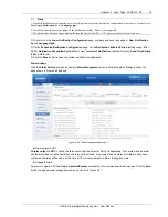
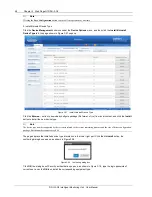
Figure 3-41 Alarm linkage configuration 2
Firstly select a command, for instance,
‘OR’. In this case, the expression is ‘signal 1 [Input1 Register] OR signal 2
[Input2 Register] = signal 3 [Output Register]
’.
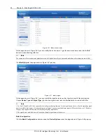
Secondly, when
Signal
is chosen for the input and output parameters, first choose the equip name from the
drop-down lists of
Equip/Register
; then choose the signal type from the drop-down lists of
Signal Type
; at last
choose the signal name from the drop-down lists of
Signal Name
; signal 1, 2, 3 can be any available signals of the
RDU-A G2-A.
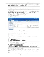
Thirdly, when
Register
is chosen for the parameters, users need to type the register name in the textbox of the
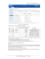
register, for instance, R(0), R(1) and so on, as shown in Figure 3-42.
Figure 3-42 Alarm linkage configuration 3
Click the
Add
button to add the new alarm linkage expression, otherwise click the
Cancel
button.
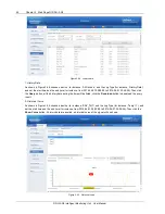
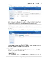
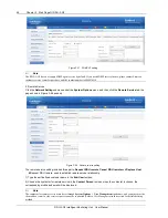
If you click the Add button, as shown in Figure 3-43, an alarm linkage expression is added. Click the
Save and Apply
button to make it effective. Click the
Delete
NMS
button to delete the PLC expression, and click the
Save and Apply
button to make the setting effective.


