Chapter 3 Web Page Of RDU-A G2 41
RDU-A G2 Intelligent Monitoring Unit User Manual
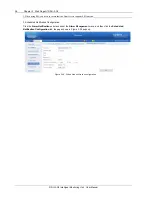
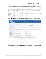
Figure 3-43 Alarm linkage configuration 3
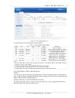
The operator usages in the alarm linkage are listed in Table 3-2.
Table 3-2 Operator usages in the alarm linkage
Operator
Input 1
Input 2
Param1
Param2
Output
Expression
SET
/
/
P1
/
Sout/Rout
SET_ _P1_Output
AND
Sin1 /Rin1
Sin2 /Rin2
/
/
Sout/Rout
Sin1 [Rin1] AND Sin2 [Rin2] = Sout [Rout]
OR
Sin1 /Rin1
Sin2 /Rin2
/
/
Sout/Rout
Sin1 [Rin1] OR Sin2[Rin2] = Sout [Rout]
NOT
Sin1 /Rin1
/
/
/
Sout/Rout
Sin1 [Rin1] NOT = Sout [Rout]
XOR
Sin1 /Rin1
Sin2 /Rin2
/
/
Sout/Rout
Sin1 [Rin1] XOR Sin2[Rin2] = Sout [Rout]
GT
Sin1 /Rin1
/
P1
P2
Sout/Rout
When Sin1 [Rin1] > P1, Sout [Rout]=1;
When Sin1 [Rin1] < P1 - P2, Sout [Rout]=0
LT
Sin1 /Rin1
/
P1
P2
Sout/Rout
When Sin1 [Rin1] < P1, Sout [Rout]=1;
When Sin1 [Rin1] > P1 + P2, Sout [Rout]=0
DS
Sin1 /Rin1
/
P1
/
Sout/Rout
Sin1 [Rin1] DS P1 output to Sout [Rout]
Note:
1. Sin1, Rin1, Sin2, Rin2, P1, P2, Sout, Rout respectively refer to Signal 1, Input1 Register, Signal 2, Input2 Register, Parameter
1, Parameter 2, Signal 3, Output Register;
2. The input signal of logic operator AND/OR/NOT/XOR/DS can only be alarm signal;
3. The input signal value of arithmetic operator GT/LT can only be float, int or long int;
4. All output signals can only be control signals, and the output signal value must be enumerated type
The following illustrates the alarm linkage with examples:
Example 1:
If it is required that when the temperature and humidity sensor of RDU-A G2 system generates a high temperature
alarm, the alarm lamp turns on. Suppose that the alarm lamp is mounted on the DO1 port, you can achieve the alarm
linkage function through the following configuration:
Expression: [High Temp 11 Alarm] DS P(3) [RDU-A DO1] [Close]
The configuration method is shown in Figure 3-44. When the High Temp 11 Alarm is generated, RDU-A DO1 will
close after a delay of 3s, thus the alarm lamp turns on.


