background image

64

VEGAPULS 56K

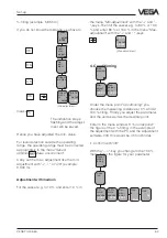
Ampl.:

XX dB

S-N:

XX dB

tion of the installation position). With the crea-
tion of a false echo storage you cause the
sensor electronics to learn the false echoes
and to save them in an internal database. The
sensor electronics treats these (false) echoes
differently than the useful echo and gates them
out.

7. Useful and noise level

In the menu

you receive important information on the signal
quality of the product echo.

The higher the amount out of "

Ampl.“ minus "S-

N“, the more reliable the measurement.

Ampl.: Means amplitude of the level echo in

dB (useful level)

S-N:

Means Signal-Noise, i.e. the level of
the background noise (noise level)

The larger the distance of the amplitude
(Ampl.) to the noise level (S-N), the better the
measurement:
> 18 dB

Measurement very good

18 … 13 dB

Measurement good

13 … 8 dB

Measurement satisfactory

8 … 5 dB

Measurement sufficient

< 5 dB

Measurement very bad

Example:

Ampl. = 68 dB

S-N = 53 dB

68 dB – 53 dB = 15 dB

15 dB signal distance mean a good reliability.

8. Outputs

Under the menu "

Outputs“ you determine if

e.g. the current output should be inverted or

Set-up

corresponding to a 100 %-filling. In the exam-
ple this would be 1200 for 1200 litres.

• Confirm with "

OK“.

If necessary, choose a decimal point. However
note that only max. 4 digits can be shown.

In the menu "

Prop. to“ you choose the param-

eter (mass, volume, distance…) and in the
menu "

Unit“ the meas. unit (kg, l, ft

3

, gal, m

3

…).

Linearisation:

A linear dependence between the percentage
value of the product distance and the percent-
age value of the filling volume is pre-adjusted.

With the menu "Lin. curve“ you can choose
between linear, spherical tank and cylindrical
tank. The adjustment of an own linearisation
curve is only possible with the PC and the
adjustment program VVO.

5. Meas. conditions

Here you choose the meas. conditions corre-
sponding to your application (see following
menu plan under no. 5).

6. False echo storage

A false echo storage is always useful when
false echo sources such as e.g. struts must be
reduced if not possible in another way (correc-

Lin.
curve

Linear

Integr
ation
time

0 s

Ad-
just-
ment

Signal
condit-
ioning

Scal-
ing

Summary of Contents for VEGAPULS 56K

Page 1: ...Level and Pressure Operating Instruction VEGAPULS 56K...

Page 2: ...respon sibility Contents Safety information 2 Note Ex area 2 1 Product description 1 1 Function 4 1 2 Application features 6 1 3 Adjustment 7 1 4 Antennas 9 2 Types and versions 2 1 Type survey 10 2 2...

Page 3: ...ipe 33 4 4 False echoes 40 4 5 Installation fault 42 5 Electrical connection 5 1 Connection and connection cable 44 5 2 Connection of the sensor 44 5 3 Connection of the external indicating instrument...

Page 4: ...This initial position defines the development aims for a high temperature radar level meas uring system of VEGAPULS 56 series A special new development of high temperature radar sensors for level meas...

Page 5: ...p to 1 second without using very time consuming frequency analysis e g FMCW necessary for other radar principles Virtually all products can be measured Radar signals physically react similar to visibl...

Page 6: ...emens 3964R Profibus DP Profibus FMS ASCII adjustment from the DCS stage Ex approvals CENELEC FM CSA ABS LRS GL LR ATEX PTB Product description ductivity or with the dielectric constant of the medium...

Page 7: ...is different hence each radar sensor must be given some basic information on the application and the environ ment The adjustment and parameter adjustment of the radar sensors are carried out with the...

Page 8: ...0 mA HART Communicator Product description Adjustment with adjustment module MINICOM With the 3 2 cm x 6 7 cm 6 key adjustment module with display you can carry out the adjustment in clear text The ad...

Page 9: ...running period of the radar sig nals changes in the pipe and depends on the pipe diameter The pipe inner diameter must be programmed in the electronics so that the running period can be compensated P...

Page 10: ...na VEGAPULS 56 DN 50 pipe antenna General features level measurement on process and products under high temperatures and high pressures measuring range 0 20 m Ex approved in Zone 1 and Zone 10 IEC or...

Page 11: ...psi 1 4571 1M2 Process connection ANSI 6 600 psi Hastelloy C22 YYY Other process connections and materials X without indication A with integral indication X without adjustment module MINICOM B with ad...

Page 12: ...o logy 4 20 mA shown without signal condition ing instrument page 18 Measuring systems with VEGAPULS 56K Two wire technology loop powered supply and output signal via one two wire line Optionally exte...

Page 13: ...T handheld VEGA CONNECT 2 Types and versions 1 If the resistors of the processing systems connected to the 4 20 mA signal output are less than 200 a resistor of 250 to 350 must be connected to the con...

Page 14: ...VEGAPULS 56K Ex0 Max resistance of the signal line 15 per wire Optionally external indicating instrument with analogue and digital indication can be mounted up to 25 m separated from the sensor Adjus...

Page 15: ...nal indicating instrument with analogue and digital indication can be mounted up to 25 m separated from the sensor in Ex area Adjustment with PC HART handheld or adjustment module MINICOM can be plugg...

Page 16: ...an be plugged into the sensor or into the external indicating instrument HART handheld VEGA CONNECT 2 Types and versions 1 If the resistors of the processing systems connected to the 4 20 mA signal ou...

Page 17: ...indicating instrument with analogue and digital indication can be mounted up to 25 m separated from the sensor in Ex area Adjustment with PC HART handheld or adjustment module MINICOM can be plugged...

Page 18: ...0 Load max 500 Types and versions active 2 VEGADIS 50 1 If the resistors of the processing systems connected to the 4 20 mA signal output are less than 200 a resistor of 250 to 350 must be connected t...

Page 19: ...ensor max 200 mW 1 2 VA Measuring range 1 Standard 0 20 m Measurement in a standpipe VEGAPULS 56 on DN 50 0 16 m VEGAPULS 56 on DN 100 0 19 m Output signal see also Outputs and processings 4 20 mA cur...

Page 20: ...0 s four wire sensor 0 3 s Min span between full and empty adjustment 10 mm recommended 50 mm Beam angle at 3 dB with DN 80 38 only for standpipe measurement with DN 100 30 only for standpipe measure...

Page 21: ...6 40 0 50 100 150 200 250 300 350 C 64 Flange DIN DN 50 Material 1 4571 groove and tongue acc to DIN 2512 form F N Flange DIN DN 80 Material 1 4571 seal surface acc to DIN 2526 form B C D E Flange DIN...

Page 22: ...0 100 150 200 250 300 350 C PN 16 PN 25 PN 40 PN 64 bar 40 25 16 64 40 0 50 100 150 200 250 300 350 C Flange DIN DN 100 Material 1 4571 seal surface acc to DIN 2526 form B C D E Flange DIN DN 100 Mate...

Page 23: ...25 16 40 0 50 100 150 200 250 300 350 C Flange DIN DN 200 Material 1 4571 seal surface acc to DIN 2526 form B C D E Flange DIN DN 250 Material 1 4571 groove and tongue acc to DIN 2512 form F N PN 16 P...

Page 24: ...K Ex classification II 2 G EEx d ia IIC T6 Ex approved Zone 1 ATEX Zone 1 CENELEC PTB IEC VEGAPULS 56K Ex0 classification II 1 2 G EEx d ia IIC T6 Ex approved Zone 0 Zone 1 ATEX Zone 0 Zone 1 CENELEC...

Page 25: ...usceptibility EN 50 082 1 1995 NSR EN 61 010 1 1993 Outputs and processings Display indication Indication optionally mounted scalable analogue and digital indication of measured values optionally exte...

Page 26: ...20 1 8 160 76 75 200 1 8 125 18 20 165 18 23 DN 50 DN 80 DN 100 320 213 185 370 205 116 25 185 213 320 370 205 116 25 3 2 Dimensions Technical data Aluminium housing Aluminium housing with Exd termina...

Page 27: ...VEGAPULS 56K 27 Technical data 22 205 146 285 DN 150 240 2 2 26 380 241 355 26 DN 250 405 24 296 197 295 22 DN 200 340...

Page 28: ...module for insertion into the sen sors VEGAPULS 56 or into the external indicat ing instrument VEGADIS 50 Size Flange Seal ledge Holes D b k d1 No d2 2 150 psi 152 4 19 0 120 7 91 9 4 19 1 3 150 psi 1...

Page 29: ...s Register of Shipping GL German Lloyd CSA Canadian Standards Association Technical data Ex area zone 0 zone 1 Series 50 sensors require for use in Ex areas special safety barriers or separators provi...

Page 30: ...erence pane empty Profiles with smooth interfering surfaces cause large false signals Round profiles diffuse the radar signals A deflector causes signal scattering Mounting and installation False refl...

Page 31: ...antenna in coni cal form similar to the beam pattern from a spotlight This emission cone angle depends on the antenna used Any object in this emission cone causes a reflection of the radar signal Wit...

Page 32: ...n into the vessel isolation and isolate it up to approx to the first pipe segment 4 2 Measurement of liquids Sensor on DIN socket piece Most of the time the mounting of radar sensors is made on short...

Page 33: ...mplified false echoes The radar sensor must be mounted outside the focus hence parabolic amplified echoes are avoided Sensor directly on the vessel top Mounting on dished end vessel 10 mm General inst...

Page 34: ...he surge or bypass pipe the max measuring range is reduced by 5 20 e g DN 50 16 m in stead of 20 m and DN 100 only 19 m instead of 20 m Direct the sensor such that the hole is in one axis with the pip...

Page 35: ...t cause measuring errors Surge pipe diameters of DN 50 to DN 150 can be con nected Standpipe measurement in inhomoge neous products Polarisation direction For reasons of radar signal polarisation the...

Page 36: ...s in one axis with the row of holes Standpipe with ball valve When using a ball valve in a surge pipe it is possible to carry out maintenance and ser vice work without opening the vessel e g with liqu...

Page 37: ...Pipe antenna systems must be provided with a vent at the upper end of a surge pipe A miss ing hole causes wrong measurements Wrong polarisation direction When measuring in a surge pipe especially when...

Page 38: ...e as measur ing pipe a stainless steel pipe without joint Extend the measuring pipe to the required length with welding neck flanges or with con necting sleeves Note that no shoulders are caused in th...

Page 39: ...ide of these sensors In agitated products fasten the measuring pipe to the vessel bottom Provide additional fastenings for longer measuring pipes With the deflector on the measuring pipe end the radar...

Page 40: ...g for material mixing with flat surface pointing to the radar sensor should be covered by a screen False echoes are hence gated out Flat shoulders Shoulders inlets Vessel installations Struts such as...

Page 41: ...roducts which can cause slight build up can be measured by using a measuring pipe with 100 mm nominal width and more In a measur ing pipe of this size slight build up is not a problem Build up If the...

Page 42: ...mm out of the socket piece Wrong directing to the product surface A directing of the sensor which does not point to the product surface will cause weak meas uring signals If possible direct the senso...

Page 43: ...here are also no interfering installa tions within the outer emission cone Note chapter 4 1 General installation instructions Emission cone and fault reflections Foam generation Strong dense and cream...

Page 44: ...as must be noted e g DIN 0165 Connection cable Note that the connection cables must be speci fied for the expected operating conditions in your systems The cable must have an outer diam eter of 5 9 mm...

Page 45: ...nication 4 20mA Display 1 2 C 5 6 7 8 4 3 ESC OK 1 2 C 5 6 7 8 4 3 L1 N Commu nication 4 20mA Display 1 2 C 5 6 7 8 4 3 4 20 mA passive 1 To the indicating instrument in the sensor cover or to the ex...

Page 46: ...er on VEGADIS 50 You can facilitate the connection procedure by fastening the housing cover during connection with one or two screws on the right of the housing figure VEGADIS 50 ESC OK 1 2 C 5 6 7 8...

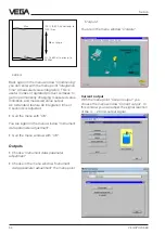
Page 47: ...sensors can be adjusted with PC adjustment program VVO detachable adjustment module MINICOM or HART handheld The adjustment must only be carried out with one adjustment medium at the same time Adjustm...

Page 48: ...arrow keys or the mouse the item Planning and click to OK You are asked for the identification Enter under the name VEGA Set up Also enter under the password VEGA The adjustment program VVO in the fo...

Page 49: ...oad resistor then 250 350 do you use VEGACONNECT instead of the new VEGACONNECT 2 Configuration Choose the menu Configuration Measuring system to get further information on the sensor type the softwar...

Page 50: ...t You can carry out the min max adjustment with medium or without medium Generally you will carry out the adjustment without medium When you want to carry out the adjustment with medium you have to ca...

Page 51: ...tage filling of a vessel is generated The characteristics points however must not be at 0 and 100 the difference should be as high as possible e g at 20 and at 80 The min distance of the characteristi...

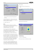
Page 52: ...ing by confirming with OK The adjustments are now transmitted to the sensor Linearisation When in your vessel there is another depend ence between product distance and the value of the filling than a...

Page 53: ...cs of the example you see four index markers or value pairs There is always a linear interpolation between the index markers Click to Show scaled values to have to ad justed meas unit displayed on the...

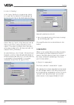
Page 54: ...ed Quit the menu with OK You are again in the menu window Instrument data parameter adjustment Quit the menu window with OK Outputs Choose Instrument data parameter adjustment Choose in the menu windo...

Page 55: ...Choose Volume percent when you want that the level of 45 1200 litres is indicated as percentage value of 0 100 Choose Distance when the actual dis tance to the product surface should be indicated in m...

Page 56: ...the sensor are permanently saved you are again in the window Meas environment First click to Meas environment With the menu point Measuring range you can define the measuring range of the sensor devi...

Page 57: ...ing to the product surface with a false echo having nearly the same size than the product echo In the following figure you see the echo curve after optimum directing to the product surface sensor axis...

Page 58: ...menu Sensor optimisation to basic adjustment Quit the menu window Sensor optimisation with Quit You are now in the entrance menu window Instrument data parameter adjustment Click to the menu point Me...

Page 59: ...0 m at 0 and 0 300 m at 100 the present signal current in the 4 20 mA signal line are displayed Simulation Click to the menu Diagnostics Simulation The menu window Display of measured value is opened...

Page 60: ...transferred later to other sensors If you have e g a plant with several equal storage vessels and identical sensors it is sufficient to configurate one sensor save the adjustments and then transfer th...

Page 61: ...ll detachable adjust ment module MINICOM The adjustment module is hence plugged into the sensor or into the external indicating instrument option ally For the adjustment with the adjustment module all...

Page 62: ...sted with the appropriate menu points in the menu plan 1 Measurement in a standpipe only carry out when you measure in a standpipe 2 Operating range 3 Adjustment 4 Conditioning 5 Meas conditions 6 Fal...

Page 63: ...or your parameter 100 0 at m d XX XXX Max adjustment OK Set up Ad just ment Pa ram eter adjust ment Sensor m d 4 700 without medium Adjust ment in m d 0 0 at m d XX XXX Min adjustment OK OK OK OK fill...

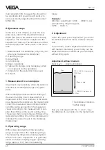
Page 64: ...ance mean a good reliability 8 Outputs Under the menu Outputs you determine if e g the current output should be inverted or Set up corresponding to a 100 filling In the exam ple this would be 1200 for...

Page 65: ...5 Set up which parameter should be provided by the sensor indication Failure indications E Hardware failure E013 No valid measured value in the inlet phase or loss of the useful echo E017 Adjustment s...

Page 66: ...spl Fail ure mode 22mA Prop to Dis tance Curr out put 4 20mA w out medium adjust ment in m d with medium 0 0 at m d 5 000 100 0 at m d 0 300 Min adjust at 0 0 Max adjust at 100 0 Sca ling Lin curve Li...

Page 67: ...numbers 1 to 5 are required The menus under the numbers 7 and 8 are only neces sary under arduous measurement conditions The menu under number 6 is only necessary for the measurement in a standpipe E...

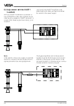
Page 68: ...handheld to the sensor signal line after you have connected the sensor to the power supply Note If the resistor of the power supply is less than 250 Ohm a resistor must be looped into the signal conne...

Page 69: ...or via a resistor acc to the following table during the HART adjustment to reach together with the inner resistor of the instrument the value of 250 Ohm required for the HART instrument VEGA signal co...

Page 70: ...70 VEGAPULS 56K Notes...

Page 71: ...VEGAPULS 56K 71 Notes...

Page 72: ...lding 505 Yardley PA 19067 7706 Tel 215 321 6012 Fax 215 321 6067 Tech Support Toll Free 866 DrLevel or 888 NIVELCO Email info DrLevel com or info hitechtech com Web Site www DrLevel com or www hitech...

Reviews: