12
VEGAPULS 56K
2
4
4 ... 20 mA
+
1)
-
> 250
2.2 Configuration of measuring
systems
A measuring system consists of a sensor with
a 4 … 20 mA-signal output and a unit
evaluating or processing the level proportional
level signal.
On the following pages you find the instrument
configurations called measuring system and
shown in the following partly with a signal
processing.
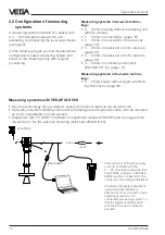
Measuring systems in two-wire techno-
logy:
• 4 … 20 mA drawing without processing unit;
(bottom picture)
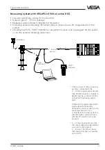
• 4 … 20 mA on active DCS;
(page 13)
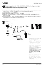
• 4 … 20 mA on active DCS in Ex-area (ia);
(page 14)
• 4 … 20 mA on passive DCS in Ex-area (ia);
(page 15)
• 4 … 20 mA on passive DCS in Ex-area (d);
(page 16)
• 4 … 20 mA on indicating instrument
VEGADIS 371 Ex;
(page 17)
Measuring systems in four-wire techno-
logy:
• 4 … 20 mA shown without signal condition-
ing instrument, (page 18)
Measuring systems with VEGAPULS 56K
• Two-wire technology (loop powered), supply and output signal via one two-wire line
• Optionally external indicating instrument with analogue and digital indication (can be mounted
up to 25 m separated from the sensor)
• Adjustment with PC, HART
®
-handheld or adjustment module MINICOM (can be plugged into
the sensor or into the external indicating instrument VEGADIS 50)
1)
If the resistors of the processing
systems connected to the
4␣ …␣ 20 mA-signal output are less
than 200
Ω
, a resistor of 250
Ω
to
350
Ω
must be connected to the
connection line during adjustment.
Otherwise the digital adjustment
signal would be extremely
damped or short-circuited via too
small input resistors of a
connected processing system so
that the digital communication
with the PC would no more be
ensured.
VEGADIS 50
VEGACONNECT
2
Types and versions

