SNOW MELT ENABLE MODULE
(See fig. s)
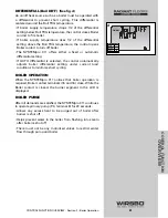
A snow melt enable module can be used to start and stop the
snow melting system. The snow melting system is enabled by
pressing the button on the front of the snow melt enable
module.
• As the slab is coming up to temperature, a green light flashes
on the front of the snow melt enable module
• Once the slab is at melting temperature and RUN TIME is
counting down, green indicator light turns solid
• To disable snow melting system when in melting mode,
press the button on the face of the snow melt enable module
• When system is stopped, a solid red indicator light is displayed
on the face of the snow melt enable module for 5 seconds
REMOTE DISPLAY MODULE
(See fig. t)
A Remote Display Module can be used to start and stop snow
melting system.
• The snow melting system is enabled by pressing the
Start
(See fig. u)
button on the Remote Display Module while in
the View Menu
• Once snow melting system is enabled, the word STRT is
displayed in the LCD for at least 5 seconds
• The Remote Display Module then displays RUN TIME setting
to allow user to adjust it
• To disable snow melting system when it is in melting mode,
press the
Stop
(See fig. v)
button on the Remote Display
Module
• The word STOP will be displayed
USING START / STOP BUTTONS
ON THE SYSTEMPRO 311
If there are no external demand modules connected to the
SYSTEMpro 311, the SYSTEMpro 311 will be used to operate
the snow melt system.
• The snow melting system is enabled by pressing the
Start
(See fig. w)
button on the SYSTEMpro 311 while in the View
Menu.
• Once snow melting system is enabled, the word STRT is
displayed in the LCD for at least 5 seconds
• The SYSTEMpro 311 then displays RUN TIME setting to
allow user to adjust it
• To disable snow melting system when it is in melting mode,
press the
Stop
(See fig. x)
button on the SYSTEMpro 311
• The word STOP will be displayed
79
CONTROL FUNCTION OVERVIEW - Section E - Snow Melting
7
9
8
s
Minimum
Maximum
Melting
en
ose
DHW
12
%
!
1
u
Item
Start
Stop
3
Minimum
Maximum
Melting
en
ose
DHW
12
%
!
1
u
Item
Start
Stop
3
w
x
CONTROL FUNCTION
OVER
VIEW
t
u
v
Summary of Contents for SYSTEMpro 311
Page 1: ...SYSTEMpro 311 Installation Manual...
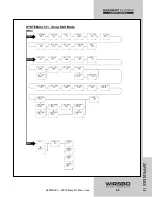
Page 90: ...88 APPENDIX II APPENDIX II SYSTEMpro 311 Menu Tree...
Page 91: ...89 APPENDIX II APPENDIX II SYSTEMpro 311 Menu Tree...
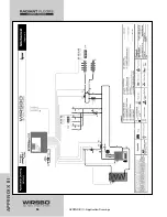
Page 92: ...90 APPENDIX III APPENDIX III Application Drawings...
Page 93: ...91 APPENDIX III APPENDIX III Application Drawings...
Page 94: ...92 APPENDIX III APPENDIX III Application Drawings...
Page 95: ...93 APPENDIX III APPENDIX III Application Drawings...
Page 96: ...94 APPENDIX III APPENDIX III Application Drawings...
Page 97: ...95 APPENDIX III APPENDIX III Application Drawings...
Page 98: ...96 APPENDIX III APPENDIX III Application Drawings...
Page 99: ...97 APPENDIX III APPENDIX III Application Drawings...
Page 106: ......


