


87
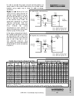
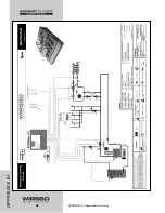
In order to provide the proper amount and temperature of
supply water on the radiant heating loop, the variable speed
injection pump needs only to inject 10 GPM at design
conditions.
Figures c and d
show the two
most common piping layouts for
variable speed injection mixing.
Pay particular attention to the drop
lines (or thermal traps) shown
in the injection legs. These are
particularly important to prevent
"thermal siphoning" from the
primary loop into the secondary
loop. Consult the pump
manufacturers' chart (below) to
assist in the selection of the proper
injection pump for the project.
In the piping arrangement shown,
the variable speed injection pumps
are plumbed in such a way as to
limit head pressure in the injection
legs to only a few feet at most.
Use standard pressure drop
calculations and equivalent length
of feet charts for exact calculations
if required.
APPENDIX I
APPENDIX I - Variable Speed Injection Mixing
To LOW
Temperature
Heating System
c
Injection into a horizontal loop
System
Pump
Balancing
Valve
Variable
Speed
Injection
Pump
Primary
Pump
From HIGH
Temperature
Loop
}
}
}
Note #2
Note #1
Note #3
}
Note #2
}
}
Note #2
Note #1
}
Note #2
To LOW
Temperature
Heating System
d
Injection into a vertical loop
System
Pump
Balancing
Valve
Variable
Speed
Injection
Pump
Primary
Pump
From HIGH
Temperature
Loop
}
}
Note #1
Note #3
}
Note #2
}
}
Note #2
Note #1
}
Note #2
Note #1 - Maximum 4 Pipe Diameters Apart
Note #2 - Minimum 6 Pipe Diameters Apart
Note #3 - Drop line to be longer than 1 foot
Note #1 - Maximum 4 Pipe Diameters Apart
Note #2 - Minimum 6 Pipe Diameters Apart
Note #3 - Drop line to be longer than 1 foot
–
1.5 - 2.0
20
0.5
X
X
X
X
X
2.5
2
100
0.5
X
4 - 5.5
3.0 - 4.5
100
0.5
X
X
X
X
X
X
4.5 - 6.5
4 - 5.5
100
0.75
X
X
9 - 10.5
7.5 - 8.5
100
0.75
X
X
X
X
9
8
100
1
X
14 - 15
12 - 13
100
1
X
X
X
19
17
100
1.25
X
22 - 24
19 - 21
100
1.25
X
X
X
26 - 28
–
100
1.5
X
X
X
35 - 37
31 - 32
100
1.5
X
X
33
30
100
2
X
41 - 45
39 - 42
100
2
X
X
Design Injection Flow Rate (US GPM)
Turns open of
Nominal Pipe
Grundfos (F)
Taco
B&G
Armstrong
Without
With
the Globe Valve
Diameter
15-42
Astro
Globe Valve
Globe Valve
(%)
(inches)
2*
3**
26
-6
4
003
007
0010
0012
NRF
9
NRF
22
NRF
33
30
50
43
-7
5
* Speed 2, ** Speed 3 (Brute)
Table courtesy of tekmar - This table assumes there are 5 feet of pipe, 4 elbows, and branch trees of the listed diameter.
These circulators have been tested and approved by the manufacturers for use with the tekmar variable speed electronics.
Manufacturer Approved Pump Models
Variable Speed Injection Design Flow Rates
Summary of Contents for SYSTEMpro 311
Page 1: ...SYSTEMpro 311 Installation Manual...
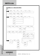
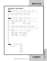
Page 90: ...88 APPENDIX II APPENDIX II SYSTEMpro 311 Menu Tree...
Page 91: ...89 APPENDIX II APPENDIX II SYSTEMpro 311 Menu Tree...
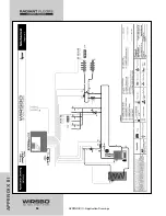
Page 92: ...90 APPENDIX III APPENDIX III Application Drawings...
Page 93: ...91 APPENDIX III APPENDIX III Application Drawings...
Page 94: ...92 APPENDIX III APPENDIX III Application Drawings...
Page 95: ...93 APPENDIX III APPENDIX III Application Drawings...
Page 96: ...94 APPENDIX III APPENDIX III Application Drawings...
Page 97: ...95 APPENDIX III APPENDIX III Application Drawings...
Page 98: ...96 APPENDIX III APPENDIX III Application Drawings...
Page 99: ...97 APPENDIX III APPENDIX III Application Drawings...
Page 106: ......