
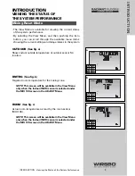


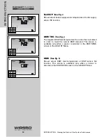


INSTALLATION - STEP 5
MOUNTING THE SENSORS
Outdoor Sensor (S4)
(See fig. a)
The Outdoor Sensor includes a 10 k
Ω
thermistor which
provides an accurate measurement of the outdoor
temperature. The
sensor is protected by a white U.V.
resistant PVC plastic enclosure.
Step One – Mounting
(See fig. b)
NOTE:
The temperature sensor (thermistor)
is built into the enclosure.
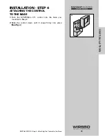
• Remove the screw and pull the front
cover off the sensor enclosure.
• The outdoor sensor can either be
mounted directly onto a wall or a 2" x 4"
electrical box. When the sensor is wall
mounted, the wiring should enter
through the back or bottom of the
enclosure. Do not mount the sensor with
the conduit knockout facing upwards as
rain could enter the enclosure and
damage the sensor.
• In order to prevent heat transmitted through the wall from
affecting the sensor reading, it may be necessary to install an
insulating barrier behind the enclosure.
• The outdoor sensor should be mounted on an exterior wall
which best represents actual outdoor temperature (a north
facing wall). It should not be exposed to heat sources such
as solar gain, exhaust ventilation or window openings.
• The outdoor sensor should be installed at an elevation
above the ground that will prevent accidental damage or
tampering. Installing the sensor in the shadow of the roof
eave is common.
Step Two – Wiring and Testing
(See fig. c)
• Connect 18 AWG or similar wire to the two terminals provided
in the enclosure and run the wires from the outdoor sensor to
the control.
CAUTION:
Do not run sensor wires parallel to
telephone or power cables. If the sensor wires
are located in an area with strong sources of
electromagnetic interference (EMI), shielded cable or
twisted pair should be used or the wires can be run
in a grounded metal conduit. If using shielded cable,
the shield wire should be connected to the Com Sen
terminal on the control and not to earth ground.
• Follow the sensor testing instructions in this brochure and
connect the wires to the control as per installation –
step 6
.
• Replace the front cover of the sensor enclosure.
20
INST
ALLA
TION
INSTALLATION - Step 5 - Mounting the Sensors
Wires from outdoor
sensor to control terminals
(Com Sen - Out Sen)
Sensor is built into
the enclosure
c
Sensor with rear
entry wiring
Sensor
with bottom
entry wiring
Sensor mounted
onto 2” x 4”
electrical box
a
b
Summary of Contents for SYSTEMpro 311
Page 1: ...SYSTEMpro 311 Installation Manual...
Page 90: ...88 APPENDIX II APPENDIX II SYSTEMpro 311 Menu Tree...
Page 91: ...89 APPENDIX II APPENDIX II SYSTEMpro 311 Menu Tree...
Page 92: ...90 APPENDIX III APPENDIX III Application Drawings...
Page 93: ...91 APPENDIX III APPENDIX III Application Drawings...
Page 94: ...92 APPENDIX III APPENDIX III Application Drawings...
Page 95: ...93 APPENDIX III APPENDIX III Application Drawings...
Page 96: ...94 APPENDIX III APPENDIX III Application Drawings...
Page 97: ...95 APPENDIX III APPENDIX III Application Drawings...
Page 98: ...96 APPENDIX III APPENDIX III Application Drawings...
Page 99: ...97 APPENDIX III APPENDIX III Application Drawings...
Page 106: ......