


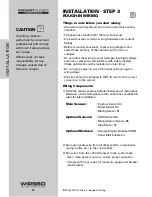


Remove the safety dividers from the wiring chamber by
pulling them straight out of their grooves.
(See fig. e)
Press the control release clip on the base inside the
wiring chamber and slide the control upwards.
(See fig. f)
The control lifts up and away from the base.
(See fig. g)
Mounting the Base
(See fig. h)
1) Find a convenient and accessible location typically in
the mechanical room
2) Following the hole pattern, mount the control base
using the appropriate screws
16
INST
ALLA
TION
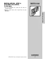
INSTALLATION - Step 2 - The Control Base
e
f
g
h
Mounting holes
Knockout
Locking Clip
Release Clip
Summary of Contents for SYSTEMpro 311
Page 1: ...SYSTEMpro 311 Installation Manual...
Page 90: ...88 APPENDIX II APPENDIX II SYSTEMpro 311 Menu Tree...
Page 91: ...89 APPENDIX II APPENDIX II SYSTEMpro 311 Menu Tree...
Page 92: ...90 APPENDIX III APPENDIX III Application Drawings...
Page 93: ...91 APPENDIX III APPENDIX III Application Drawings...
Page 94: ...92 APPENDIX III APPENDIX III Application Drawings...
Page 95: ...93 APPENDIX III APPENDIX III Application Drawings...
Page 96: ...94 APPENDIX III APPENDIX III Application Drawings...
Page 97: ...95 APPENDIX III APPENDIX III Application Drawings...
Page 98: ...96 APPENDIX III APPENDIX III Application Drawings...
Page 99: ...97 APPENDIX III APPENDIX III Application Drawings...
Page 106: ......