background image

SonixTablet Service Manual

00.053.129, Revision C

Table of Contents

i

TABLE OF CONTENTS

CHAPTER 1: GENERAL INFORMATION...................................................................................................................................................... 1-1

1.1

AUDIENCE................................................................................................................................................................................................... 1-1

1.1.1

Prescription Device................................................................................................................................................................................ 1-1

1.2

VOLTAGE DISCLAIMER.............................................................................................................................................................................. 1-1

1.3

CONNECTIVITY DISCLAIMER.................................................................................................................................................................... 1-1

1.4

PRIVACY DISCLAIMER............................................................................................................................................................................... 1-1

1.5

SERVICE DISCLAIMER............................................................................................................................................................................... 1-1

1.6

SYSTEM HANDLING  .................................................................................................................................................................................. 1-2

1.7

LICENSE AGREEMENT .............................................................................................................................................................................. 1-2

1.8

TRADEMARKS AND PATENTS .................................................................................................................................................................. 1-2

1.9

SYSTEM OVERVIEW .................................................................................................................................................................................. 1-2

1.10 PHYSICAL DESCRIPTION .......................................................................................................................................................................... 1-4

1.10.1

LCD Display/Touch Screen.................................................................................................................................................................... 1-4

1.10.2

Operator Console .................................................................................................................................................................................. 1-4

1.10.3

Modulo................................................................................................................................................................................................... 1-4

1.10.4

Transducers........................................................................................................................................................................................... 1-4

CHAPTER 2: SYSTEM SPECIFICATIONS.................................................................................................................................................... 2-1

2.1

DIMENSIONS............................................................................................................................................................................................... 2-1

2.2

ELECTRICAL RATINGS .............................................................................................................................................................................. 2-1

2.3

VOLTAGE ADJUSTMENT ........................................................................................................................................................................... 2-1

CHAPTER 3: SYSTEM INSTALLATION........................................................................................................................................................ 3-1

3.1

INSTALLATION ISSUES AND REQUIREMENTS ....................................................................................................................................... 3-1

3.1.1

Environmental Requirements ................................................................................................................................................................ 3-1

3.1.2

Electrical Requirements......................................................................................................................................................................... 3-2

3.1.2.1 Instrument Input Power Rating .......................................................................................................................................................... 3-2

3.1.3

Electrostatic Discharge.......................................................................................................................................................................... 3-3

3.1.4

Electromagnetic and Radio Frequency Interference ............................................................................................................................. 3-3

3.1.5

Wiring Requirements ............................................................................................................................................................................. 3-4

3.1.5.1 Main AC Connection.......................................................................................................................................................................... 3-4
3.1.5.2 Ethernet (Hard-Wired) Network Connection...................................................................................................................................... 3-4
3.1.5.3 Image Management Network ............................................................................................................................................................ 3-4

3.2

PRE-INSTALLATION ................................................................................................................................................................................... 3-5

3.2.1

Preliminary Inspection ........................................................................................................................................................................... 3-5

3.2.2

SonixTABLET Unpacking Instructions................................................................................................................................................... 3-5

3.3

INSTALLATION............................................................................................................................................................................................ 3-8

3.3.1

EMI Filter and Power Pack .................................................................................................................................................................... 3-8

3.3.1.1 Voltage Configuration ........................................................................................................................................................................ 3-8

3.3.2

Powering the System........................................................................................................................................................................... 3-10

3.3.2.1 Turning on Main Power Switch........................................................................................................................................................ 3-10
3.3.2.2 Changing Fuses ...............................................................................................................................................................................3-11

3.3.3

Transducer Inspection ......................................................................................................................................................................... 3-12

3.3.4

System Initialization............................................................................................................................................................................. 3-12

3.3.5

Peripherals .......................................................................................................................................................................................... 3-13

3.3.5.1 Barcode Reader .............................................................................................................................................................................. 3-13

CHAPTER 4: PERFORMANCE TESTING ..................................................................................................................................................... 4-1

4.1

CONSOLE TEST .......................................................................................................................................................................................... 4-1

4.2

IMAGE TEST ................................................................................................................................................................................................ 4-2

4.3

REMOVABLE HARDWARE (IF APPLICABLE) ........................................................................................................................................... 4-2

4.4

PULSED DOPPLER SOUND TEST ............................................................................................................................................................. 4-3

4.5

LICENSES.................................................................................................................................................................................................... 4-3

Summary of Contents for SonixTablet

Page 1: ...SonixTablet Ultrasound System Service Manual...

Page 2: ......

Page 3: ...nix Medical Corporation 130 4311 Viking Way Richmond BC V6V 2K9 Canada www ultrasonix com 1 866 437 9508 1 604 279 8550 1 778 296 3860 Support 2013 Ultrasonix Medical Corporation 00 053 129 Revision C...

Page 4: ......

Page 5: ...nmental Requirements 3 1 3 1 2 Electrical Requirements 3 2 3 1 2 1 Instrument Input Power Rating 3 2 3 1 3 Electrostatic Discharge 3 3 3 1 4 Electromagnetic and Radio Frequency Interference 3 3 3 1 5...

Page 6: ...Data via the Service Mode Option 7 7 7 1 6 Restoring Importing Patient Data via the Service Mode Option 7 9 7 1 7 Connectivity 7 11 7 1 7 1 Side Connectivity Panel 7 11 7 2 INTERNAL COMPONENT REPLACEM...

Page 7: ...ing Non Invasive Transducers 11 11 11 3 5 2 Disinfecting Non Invasive Transducers 11 11 11 3 6 Cleaning Disinfecting Endocavity Transducers 11 12 11 3 7 Sterilization 11 13 11 4 SHIPPING TRANSDUCERS F...

Page 8: ...ting A 3 A 4 2 Check the Clarity License Status A 3 A 4 3 Re Import License txt A 3 A 5 IMAGE HAS THREE 3 UNIFORM BLACK AREAS LEFT MIDDLE RIGHT A 4 A 5 1 Test US Module A 4 A 6 REGEDIT ENSURE SETTINGS...

Page 9: ...SonixTablet Service Manual 00 053 129 Revision C List of Service Drawings i LIST OF SERVICE DRAWINGS Hard Drive Removal D 3 Hard Drive Removal D 4 System Filter Removal Replacement D 5...

Page 10: ...List of Service Drawings 00 053 129 Revision C SonixTablet Service Manual ii...

Page 11: ...tions that may not be available on all platforms Therefore some service instructions will apply only to specific models configurations Caution United States law restricts this device to sale or use by...

Page 12: ...relief will be appropriate to restrain such use threatened or actual Buyer further agrees that i any of the Ultrasonix suppliers of software is a direct and intended beneficiary of this end user subli...

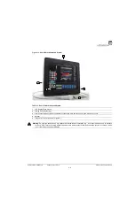
Page 13: ...ctivity Panel power and Network connections USB and sound ports and Hard Drive access 4 Speaker 5 Transducers connected at rear of system Warning Do not place the device on any surface that blocks res...

Page 14: ...em controls are touch screen based 1 10 3 Modulo The modulo which is the heart of the system is enclosed in the case with the LCD display touch screen The 1 10 4 Transducers Ultrasonix offers a wide s...

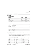
Page 15: ...x 5 8 cm 4 1 in x 15 75 in x 2 3 in Power Pack Weight 2 7 kg 6 95 lbs Input 100V 120V 50 60 Hz 200V 240V 50 60 Hz Power Rating 120 VAC 7 0A 240 VAC 4 0A Fuse Type 7A 250V SLO BLO Fuse Size 6 4 mm x 31...

Page 16: ...China 220V Libya 110 220V Tahiti 110V Columbia 110V Luxembourg 110 220V Taiwan 110V Costa Rica 110V Macao 220V Tanzania 220V Cuba 110V Madeira 220V Thailand 220V Cyprus 220V Majorca 110 220V Trinidad...

Page 17: ...scal 50 kPa to 106 kPa kilopascal Warning Operate in an indoor environment only free from moisture flammable liquids gases corrosive substances strong electrical or magnetic fields and equipment that...

Page 18: ...an equivalent hospital grade socket The specifications of the hospital grade power cord as follows Table 3 6 Hospital Grade Power Cord Specifications Electrical Rating Value Measurement System Only 10...

Page 19: ...ch as an ESD strap 3 1 4 Electromagnetic and Radio Frequency Interference This equipment has been tested and found to comply with the EMC limits for EN 55011 Group 1 Class A and EN 60601 1 2 These lim...

Page 20: ...is CAT5 Category 5 10 Base T unshielded twisted pair 3 1 5 3 Image Management Network Obtain the following information from the system administrator list of all equipment that is part of the Image Ma...

Page 21: ...the carrier and Ultrasonix 3 2 2 SonixTABLET Unpacking Instructions Equipment Tools Required scissors or utility knife To Unpack the System 1 Ensure the top of the system box is facing in the correct...

Page 22: ...the foam packing in one piece setting it gently on a solid flat surface 8 Gently pull the foam packing away from the sides of the SonixTablet Warning Although the SonixTablet is portable it weighs mo...

Page 23: ...sealing it 2 Remove the transducer case s Warning Do not place the device on any surface that blocks restricts ventilation e g do not set the device on a soft surface such as a bed Failure to comply...

Page 24: ...2 2 for details on how to remove the fuse box and replace the fuse s When changing the voltage settings the EMI filter must be adjusted to the relevant setting and the fuses must be flipped to match t...

Page 25: ...e Settings 1 Power off and unplug the power cord from both the wall outlet and the system 2 Use the screwdriver to open the fuse box lid 3 Position the screwdriver at the top as in step 2 using it to...

Page 26: ...he power cord into a wall outlet hospital grade electrical outlet recommended 3 3 2 1 Turning on Main Power Switch To Turn on Main Power Switch 1 Press the Main Power switch on the back of the Power P...

Page 27: ...plug the power cord from both the wall outlet and the system 2 Use the screwdriver to open the fuse box lid 3 Position the screwdriver at the top as in step 2 using it to remove the fuse box 4 Replace...

Page 28: ...e to the system and report it to Ultrasonix 2 Connect at least one transducer to the system 3 Plug in the power cord 4 Press and hold the console POWER button for one 1 second 5 Inform the facility s...

Page 29: ...report the damage to Ultrasonix To connect configure the printer refer to Chapter 6 Peripherals and Accessories 3 3 5 1 Barcode Reader To connect the barcode reader plug the reader s USB connector in...

Page 30: ...Chapter 3 System Installation 00 053 129 Revision C SonixTablet Service Manual 3 14...

Page 31: ...l items During these tests the system should be running in normal operating mode 4 1 CONSOLE TEST To ensure the console is functioning properly test the console and touch screen buttons dials listed i...

Page 32: ...e system as a default package The following comprises a list of the supported removable hardware medical grade USB printer medical grade Footswitch barcode reader USB media memory stick external hard...

Page 33: ...crease the volume or the bottom to decrease it 8 The sound of static should be audible 4 5 LICENSES Check to ensure the system is configured with at least some Active licenses If no licenses are Activ...

Page 34: ...Chapter 4 Performance Testing 00 053 129 Revision C SonixTablet Service Manual 4 4...

Page 35: ...o the Update Location Internet Update 5 From the Available Updates drop down menu select the appropriate software version 6 Select Update 7 The system will automatically download the version specified...

Page 36: ...copy it onto some type of USB media memory stick external hard drive etc 2 Connect the USB device to one of the system s four 4 external USB ports 3 Tap the touch screen button 4 Select Administrator...

Page 37: ...tor Patient Repair Database 3 Select OK to exit 5 3 SYSTEM RECOVERY Before performing a system recovery consult an Ultrasonix Technical Support Representative as this should only be done as a last res...

Page 38: ...Chapter 5 Software 00 053 129 Revision C SonixTablet Service Manual 5 4...

Page 39: ...Configure Custom Keys 6 1 3 and Image Sheet Printing 6 1 3 3 as required 6 1 2 Network Printer Setup This section uses the HP DeskJet 5440 as the example Network Printer and is meant only as a guide a...

Page 40: ...2 4 Select Next 5 Select Browse for a printer 6 Select Next 7 Select the appropriate shared network printer and select Next 8 Select Yes to continue 9 Select Yes to set the selected printer as the de...

Page 41: ...s 3 Select the desired Custom Key tab 4 Select the Printer checkbox 5 Select OK 6 1 3 2 Trigger Configuration To Configure the Custom Key Function for Trigger 1 Tap the touch screen button 2 Select Ad...

Page 42: ...al commands as required enter the desired text in the space provided 7 Select OK Note The default is set to print as two 2 columns by three 3 rows for a total of six 6 images per sheet Before the prin...

Page 43: ...lity in your area Table 6 2 Transducers SA4 2 24 Phased Array BPC8 4 10 Curved Array BPL9 5 55 Linear Array PA7 4 12 Phased Array L9 4 38 Linear Array mTEE8 4 5 Phased Array L14 5 38 and L14 5 38 GPS...

Page 44: ...Chapter 6 Peripherals and Accessories 00 053 129 Revision C SonixTablet Service Manual 6 6...

Page 45: ...ng the modulo export User Data to an external USB backup medium memory stick external hard drive etc This will ensure access to this data if either the modulo or hard drive needs replaced during servi...

Page 46: ...screen button 4 Select Administrator System Export 5 Check the item s to be exported 6 Select OK to begin the export process or Cancel to exit without exporting 7 If OK is selected in step 6 a comple...

Page 47: ...ystem The following options are available for import Imaging Presets 3D 4D Presets DICOM Server Configuration Settings Measurement Order Obstetrical Tables Protocols General Preset Assignments Measure...

Page 48: ...ly created backup into one of the six 6 USB ports 3 Tap the touch screen button 4 Select Administrator System Import 5 Check the items to be imported 6 Select OK to begin the import process or Cancel...

Page 49: ...e Export Destination 6 Select the Export button to begin the backup 7 When the Export is complete the following message will be presented Note When creating a backup prior to servicing the modulo be s...

Page 50: ...he left hand side of the Exam Import Export page select all data for import 5 Select the Import button to begin the procedure 6 When the Import is complete the following message will be presented Note...

Page 51: ...rnal hard drive etc with at least 5 Gb of available space To Backup Export Patient Data via the Service Mode Option 1 Connect the USB keyboard to the one of the four 4 USB ports 2 Connect the USB stor...

Page 52: ...Data Backup Restore 8 Select Go 9 Select Backup 10 If the USB device already contains patient data the following message will be displayed Select OK to continue or Cancel to exit without creating a ba...

Page 53: ...the USB keyboard to the one of the four 4 USB ports 2 Connect the USB storage device to the one of the three 3 remaining USB ports 3 Tap the touch screen button 4 Select Administrator Service 5 Type...

Page 54: ...ntInfo folder already exists on the system the following warning will be presented Select Yes to continue or No to exit without restoring Patient Exam data 11 When Patient Exam data already exists on...

Page 55: ...e Connectivity Panel Figure 7 2 Side Connectivity Panel Table 7 3 Side Connectivity Panel Sound Connections Line in blue may be used to connect an Ultrasonix approved audio input device System Speaker...

Page 56: ...er to the protect the integrity of the client s data IMPORTANT The contents of the system hard drive may include Personal Health Information that must be protected as dictated by local or state laws f...

Page 57: ...Using a 2 5mm Allen key remove the two 2 screws securing the hard drive cover 2 Using a 1 Phillips screwdriver remove the two 2 screws and washers securing the hard drive cover plate 3 Using your fin...

Page 58: ...ard Drives To Replace the Hard Drives 1 Using your fingers insert the hard drives in the relevant slots 2 Replace the hard drive cover plate and using a 1 Phillips screwdriver fasten it with the two 2...

Page 59: ...s USE OF CONTROLS or adjustments or performance of procedures other than those specified in the manufacturer s User s Guide delivered with system may result in hazardous laser light exposure NEVER att...

Page 60: ...tem 2 Tap the touch screen button and select the relevant transducer 3 Gently slide the edge of any coin along the transducer face to test for a line s or shadow s in the image on the LCD display 4 If...

Page 61: ...ant transducer 4 Test the transducer by taking a fresh image If the line shadow s in the image disappears then the transducer board is the problem and the front block ultrasound module rather than the...

Page 62: ...instructions appropriate shipping method instructions and destination Ultrasonix Technical Support Toll Free 1 866 437 9508 Canada and USA Telephone 1 604 279 8550 dial 3 E mail support ultrasonix co...

Page 63: ...8 1 DICOM Configuration Note DICOM Structured Reporting is supported Refer to Table 8 2 for Structured Reporting data transfer options Notes When using a hard wired network connection ensure the netw...

Page 64: ...touch screen button 2 Select Administrator DICOM 3 Configure the global settings as required Local Host Station Name General DICOM Station Name AE Title AE Application Entity Title of the Sonix system...

Page 65: ...ur 4 tabs will be presented AE Configuration Global Storage Settings Brightness Contrast and SonixHUB Settings 4 Create select a Device Name Edit the Application Entity AE settings for the selected De...

Page 66: ...a entered edited in the following fields is specific to the selected Device Name AE Title AE Title of the Storage SCP IP Address Unique identifier of Storage SCP Port Listening Port of the Storage SCP...

Page 67: ...details on image formats Multi Frame JPEG Lossy JPEG Lossless JPEG Lossless SV1 RLE Lossless No Compression Set DICOM image format storage order for Cine loops Note Refer to the DICOM Standard for det...

Page 68: ...to enable the display of DICOM Storage error messages e g Failed to connect to DICOM Schedule Select an auto transfer setting End of Exam Immediate On Idle Storage Folder Select the location local or...

Page 69: ...ages Figure 8 6 DICOM Storage Settings Brightness Contrast Table 8 5 DICOM Storage Settings Brightness Contrast Contrast Adjusts the level of Contrast applied to the images Brightness Adjusts the leve...

Page 70: ...tings SonixHUB Settings Table 8 6 DICOM Storage Settings Global Storage Settings Note These settings are only available if SonixHUB is licensed Embed Cine As Is Select to send Cine files in AVI format...

Page 71: ...presented AE Configuration and Brightness Contrast 4 Create select a Device Name Edit the Application Entity AE settings for the selected Device 5 Repeat step 4 as many times as required 6 Configure...

Page 72: ...Select to Add the new AE Print Device Delete Select to Delete the selected AE Print Device Test Select to send verification request to DICOM Print Device ping to verify connection Settings Select to a...

Page 73: ...mages in color Deselect to print grayscale default Columns Select the number of Columns per page Rows Select the number of Rows per page Film Session Attributes Number of Copies Select the Number of C...

Page 74: ...rinter specific and only available if Cubic Magnification is selected in the previous field Trim Select Yes or No to use a border Trim on each page Configuration Enter printer specific Configuration i...

Page 75: ...images Figure 8 11 DICOM Print Settings Brightness Contrast Table 8 10 DICOM Print Settings Brightness Contrast Contrast Adjusts the level of Contrast applied to the images Brightness Adjusts the lev...

Page 76: ...gs AE Configuration Devices Use the Devices option to add as many DICOM Worklist Servers as required Name Enter select the Name of an AE Worklist Device and populate the three 3 AE fields AE Title IP...

Page 77: ...on requires a third party USB modem Contact your dealer or Ultrasonix Technical Support to learn more about this option Caution System networking options are intended for use inside your organization...

Page 78: ...enable Online Support Add Use to Add extra non Ultrasonix Online Support IP addresses Note Ultrasonix Online Support addresses are added automatically Delete Use to Delete extra non Ultrasonix Online...

Page 79: ...tings 6 Under General select Obtain an IP address automatically or Use the following IP address and enter the assigned static IP address Subnet mask and Default gateway 7 Select OK and exit the Menu s...

Page 80: ...x has been selected 6 Complete the Account Information and Options sections Phone Number Username Password and Timeout 7 Select OK and exit the Menu system 9 1 2 1 Dialup Communication Test To Perform...

Page 81: ...uration Page Wireless Figure 9 5 Wireless Network Connection Setup Note Not available on the SonixOP platform Notes Wireless Network Connection options are controlled by MS Windows not Ultrasonix Once...

Page 82: ...he menu system 9 1 3 1 Wireless Communication Test To Perform a Wireless Communication Test 1 Tap the touch screen button 2 Select Online Support This should connect the system to an Ultrasonix Techni...

Page 83: ...screen button 2 Select Remote Support 3 Enter the PIN Personal Identification Number provided by Ultrasonix Technical Support 4 When prompted select Download Run Run in order to install the required...

Page 84: ...Chapter 9 Network Configuration 00 053 129 Revision C SonixTablet Service Manual 9 8...

Page 85: ...ia memory stick external hard drive etc To Obtain and Copy License txt onto the System 1 Tap the touch screen button 2 Select Administrator Licensing 3 Make note of the System Identification Number sh...

Page 86: ...e touch screen button 2 Select Administrator Licensing 3 Select Local Drive 4 Under the Look in drop down menu select the drive containing license txt for example data_1 D 5 Highlight license txt and...

Page 87: ...performance or unexpected breakdown The following table offers recommendations that must be weighed by factors like frequency of use and environmental conditions In every case frequent checks of safe...

Page 88: ...brasive cloth and wipe down the cabinet 50 50 isopropyl alcohol and water any proprietary glass cleaning solution water mild detergent PH level at or near 7 and water solution 11 2 2 Power Pack Apply...

Page 89: ...ter When Connected Externally Apply a small amount of one of the following recommended cleaning solutions to a soft non abrasive cloth and wipe the wireless adapter water mild detergent PH level at or...

Page 90: ...helps to safely prolong the modulo fan filter cleaning interval refer to Table 11 1 for the various maintenance procedure frequencies Use a vacuum cleaner to remove the dust from the system exhaust f...

Page 91: ...protect the LCD display touch screen gently tip the system flat 3 Unscrew the two 2 thumbscrews and washers 4 Push the filter forward following the directional arrow label then lift up 5 Vacuum thoro...

Page 92: ...cracks or other damage to the transducers before they are used Inspect the transducer surfaces for cracks and feel for cracks with finger tips as well Where any transducer including but not limited t...

Page 93: ...that contain perfume If there are any questions contact Ultrasonix Medical Corporation Gel Name Manufacturer Address Aquasonic 100 Parker Laboratories Inc 286 Eldridge Road Fairfield NJ 07004 USA Ph 8...

Page 94: ...autions DO NOT drop the transducers DO NOT hit the transducers against any surface that can dislodge or damage any of the transducer components DO NOT pinch or kink the transducer cable DO NOT use a b...

Page 95: ...luding safety procedures involving personal protective equipment such as gloves protective eyewear and protective clothing DO NOT use sterilization or disinfection methods that have not been recommend...

Page 96: ...NTS 75 IPA Cidex Activated Dialdehyde Solution 14 day Cidex Plus 28 day Cidex OPA Cidezyme Klenzyme McKesson Brand Metrizyme Milton Disinfecting Liquid Nuclean Omnicide FG2 T spray M ISCELLANEOUS SA4...

Page 97: ...leaning always remove covers accessories and attachments To Clean a Transducer 1 After every patient exam wipe the ultrasound transmission gel off the transducer 2 Wipe the transducer and cable with a...

Page 98: ...instructions on cleaning disinfecting the mTEE8 3 5 transducer refer to the most recent Sonix Ultrasound System mTEE8 3 5 User Manual ENDOCAVITY TRANSDUCERS CLEANING DISINFECTING AGENTS Cidex Activate...

Page 99: ...ansducer is disinfected prior to shipping 11 3 5 and 11 3 6 the transducer is properly packaged for shipment 11 3 3 2 all shipping waybills paperwork is completed as per the relevant regulations and l...

Page 100: ...Chapter 11 Maintenance 00 053 129 Revision C SonixTablet Service Manual 11 14...

Page 101: ...2 2 Changing Fuses 3 3 1 1 Voltage Configuration If the system still does not power on contact Ultrasonix Technical Support 12 2 SYSTEM HAS POWER BUT IS NOT POWERING UP The system has power if when p...

Page 102: ...2 Check Custom Keys Settings A 3 3 Check DICOM Settings A 3 4 Clear DICOM Settings System may require data and file folder cleanup 7 1 3 Exporting Patient Exam Data As Required A 3 5 Delete Older LUTS...

Page 103: ...Re Import License txt Check to ensure the transducer is not defective test the transducer on another system and compare images submit test images for diagnosis to Ultrasonix Technical Support 12 8 IMA...

Page 104: ...an image that has there are three 3 uniform and evenly spaced dark areas likely has a faulty Ultrasound US Module board Test and if necessary replace the US Module A 5 1 Test US Module 12 11 REGEDIT S...

Page 105: ...sful Initialization Image 12 13 1 Electronics Initialization Failure Contact Ultrasonix Technical Support 12 13 2 Memory Tests Failure at Initialization Use A 7 1 Electronics Initialization Failure Ha...

Page 106: ...connected contact Ultrasonix Technical Support 12 14 NO NETWORK CONNECTION VIA ETHERNET CABLE If the system is connected to the network via an Ethernet cable but a network connection cannot be establi...

Page 107: ...TEM POWERS ON LCD DISPLAY SHOWS MBR ERROR 1 To Resolve the MBR Error 1 Issue 1 Power down and unplug the system 2 Using the instructions in 7 2 1 Removing the Hard Drives access the hard drives and re...

Page 108: ...orer select Go 5 Go to D PateintInfo 6 Look for file dcm_storage_queue xml and dcm_print_queue xml 7 Right click on the two files using the Update key then select Delete 8 Reboot the machine A 3 5 Del...

Page 109: ...utton 2 Select Administrator Licensing 3 Ensure the Status for the Clarity License is set to Enabled A 4 3 Re Import License txt To Re Import License txt 1 Insert the USB device with license txt file...

Page 110: ...s fails to solve the problem contact Ultrasonix Technical Support A 6 REGEDIT ENSURE SETTINGS ARE CORRECT To Edit REGEDIT 1 Ensure a USB keyboard is connected to the system 2 Press the WINDOWS START K...

Page 111: ...er 7 In Windows Explorer go to C Program files Ultrasonix Exam and double click Hwtest exe 8 Select Initialize and wait for the results 9 Select Test and highlight the text in the results box using th...

Page 112: ...ll transducers 2 Reconnect one 1 transducer 3 Restart the system 4 If the problem persists contact Ultrasonix Technical Support A 7 3 System Hangs When Loading Maps at Initialization Troubleshooting t...

Page 113: ...BIOS 3 Select BIOS Integrated Peripherals Gbe Controller 4 Select Disabled To Configure a Static IP Address 1 Ensure a USB keyboard is connected to the system 2 Press the WINDOWS START KEY and select...

Page 114: ...t Service Manual A 8 A 9 TRANSDUCER CONNECTION PORT NOT FUNCTIONING To Confirm MUX Board Needs Replacing 1 Disconnect all transducers 2 Reconnect only one 1 transducer 3 Restart the system 4 If the tr...

Page 115: ...mmunity Test IEC 60601 Test Level Compliance Level Electromagnetic Environment Guidance Electrostatic discharge ESD IEC 601000 4 2 6 kV contact 8 kV air 6 kV contact 8 kV air Floors should be wood con...

Page 116: ...FM radio broadcast and TV broadcast cannot be predicted theoretically with accuracy To assess the electromagnetic environment due to fixed RF transmitters an electromagnetic site survey should be cons...

Page 117: ...very Ultrasonix shall have no responsibility for defects in materials or workmanship of any Product after the expiry of the applicable period for each aspect of the Limited Warranty In the event that...

Page 118: ...Appendix C Ultrasonix Limited Warranty 00 053 129 Revision C SonixTablet Service Manual C 2...

Page 119: ...l 00 053 129 Revision C Appendix D Service Drawings D 1 APPENDIX D SERVICE DRAWINGS Caution Service drawings do not include cable connections Please refer to the relevant sections in this Service Manu...

Page 120: ...Appendix D Service Drawings 00 053 129 Revision C SonixTablet Service Manual D 2...

Page 121: ...Solid State Hard Drive UXID 00 034 097 Patient Data Hard Drive UXID 00 034 105 M4 x 10 Button Head Screw x2 UXID 00 031 321 Tool 2 5mm Allen key Hard Drive Cover UXID 00 038 227 SonixTablet SXTAB1 0...

Page 122: ...51 Solid State Hard Drive UXID 00 034 097 Patient Data Hard Drive UXID 00 034 105 M4 x 10 Button Head Screw x2 UXID 00 031 321 Tool 2 5mm Allen key Hard Drive Cover UXID 00 038 227 SonixTablet SXTAB1...

Page 123: ...400 2 Slide Air Filter UXID 00 032 194 Caution Before removing the filter gently lay the system face down on a protective mat such as bubble wrap or a soft towel System Filter Removal Replacement Son...

Reviews: