


33
D. Stainless Steel Venting
Warning
asphyxiation Hazard. Follow these instructions
and the installation instructions included by
the original stainless steel venting component
manufacturers, Heat Fab, M&g/DuraVent or
Z-Flex, whichever applicable. Failure to do so
could cause products of combustion to enter the
building, resulting in severe property damage,
personal injury or death. Where a conflict arises
between Heat Fab, M&g/DuraVent or Z-Flex
instructions and these instructions, the more
restrictive instructions shall govern.
Do not mix vent components from listed
manufacturers.
Examine all components for possible
shipping damage prior to installation.
all condensate that forms in the vent must be
able to drain back to the boiler.
nOTiCE
Do not exceed maximum vent/combustion
air system length. refer to “2. Vent/
Combustion air Piping” under “a. general
guidelines” in this section for maximum
vent/combustion air system length.
Use only vent and combustion air terminals
and terminal locations shown in “3. Vent/
Combustion air Terminals” under “a.
general guidelines” of this section.
1. Components
a. For use on models ALP399C and ALP500C, U.S.
Boiler Company offers size 4 in. vent pipe and
fittings shown in Table 19. It is the responsibility
of the installing contractor to procure stainless
steel vent system pipe and related components.
iV. Venting
(continued)
b. Alternate listed stainless steel vent system
manufacturers and components are shown in
Tables 20 and 21.
c. Where the use of “silicone” is called for in the
following instructions, use GE RTV 106 or
equivalent for the vent collar. Seal galvanized
combustion air piping sections with any general-
purpose silicone sealant such as GE RTV102.
Seal PVC combustion air piping sections with
PVC cement.
d. Do not drill holes in vent pipe.
2. Field Installation of Stainless Steel Vent
Adapter
(see Figure 22)
a. No adapter is required for stainless steel vent
pipe unless vent diameter is reduced per Table 8.
See Table 19, 20, or 21 for adapters for reduced
vent diameter.
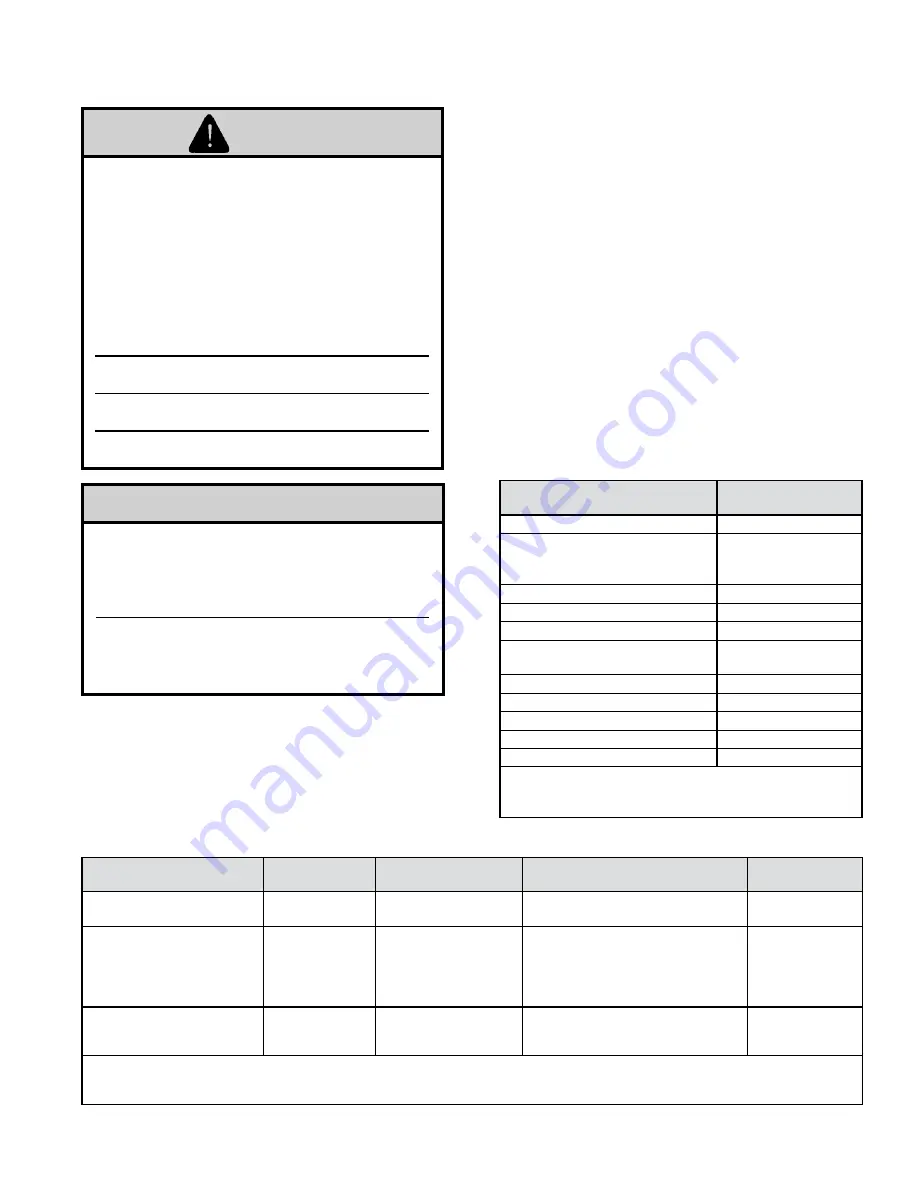
Table 19: U.S. Boiler Company (Heat Fab)
Vent System Components
(Stainless Steel, 4 in. only)
Component
Part number, 4 in.
(100 mm)
Boiler Adapter
no adapter required
Sidewall
*
or Roof Termination:
Straight
Termination w/Screen
102680-02
Straight Pipe, 1 ft. (0.3 m)
100176-01
Straight Pipe, 3 ft. (0.9 m)
100177-01
Straight Pipe, 5 ft. (1.5 m)
100178-01
Straight Pipe, Adjustable
1.06-1.64 ft. (0.3 m to 0.5 m)
100179-01
90° Elbow
100180-01
45° Elbow
100181-01
Horizontal Drain Tee
100182-01
Vertical Drain Tee
100183-01
Single Wall Thimble
100184-01
* note
: when using room air for combustion, use tee for
sidewall vent termination.
Tee part number: 8116313 (4 in.).
Boiler Model
nominal Pipe
Diameter
Boiler adapter
Sidewall * or roof Termination:
Straight Termination w/Screen
Wall Thimble
ALP399C (reduced dia.)
ALP500C (reduced dia.)
3 in. (80 mm)
FS0403TR
FSBS3
FSWT3
ALP399C (standard dia.)
ALP500C (standard dia.)
ALP600C (reduced dia. vent)
ALP700C (reduced dia. vent)
ALP800C (reduced dia. vent)
4 in. (100 mm)
ALP399C & ALP500C:
No Adapter Required;
ALP600C, ALP700C,
ALP800C: FS0604TR
FSBS4
FSWT4
ALP600C (standard dia. vent)
ALP700C (standard dia. vent)
ALP800C (reduced dia. vent)
6 in. (150 mm)
No Adapter Required
FSBS6 (23° angle)
FSWT6
note:
When using room air for combustion, use tee for sidewall vent termination. Termination tee part numbers: FSTT3 (3 in.),
FSTT4 (4 in.) FSTT6 (6 in.)
See M&G DuraVent FasNSeal literature for other required component part numbers such as straight pipe, elbows, firestops, and vent supports.
Table 20: M&g DuraVent FasnSeal Stainless Steel Vent System Components, Single Wall
Summary of Contents for Alpine ALP500C
Page 48: ...48 VI Water Piping and Trim continued Figure 28 Near Boiler Piping Heating Only ...
Page 62: ...62 Figure 40 Ladder Diagram VIII Electrical continued ...
Page 63: ...63 VIII Electrical continued 2 Figure 41 Wiring Connections Diagram ...
Page 72: ...72 IX System Start up continued Figure 48 Operating Instructions ...
Page 124: ...124 XIII Repair Parts continued ...
Page 126: ...126 XIII Repair Parts continued ALP600C ALP700C and ALP800C ALP800C shown ...
Page 130: ...130 XIII Repair Parts continued ...
Page 133: ...133 XIII Repair Parts continued 10A 10B 10C 10D 10G ...
Page 143: ...143 ...
Page 144: ...144 U S Boiler Company Inc P O Box 3020 Lancaster PA 17604 1 888 432 8887 www usboiler net ...


