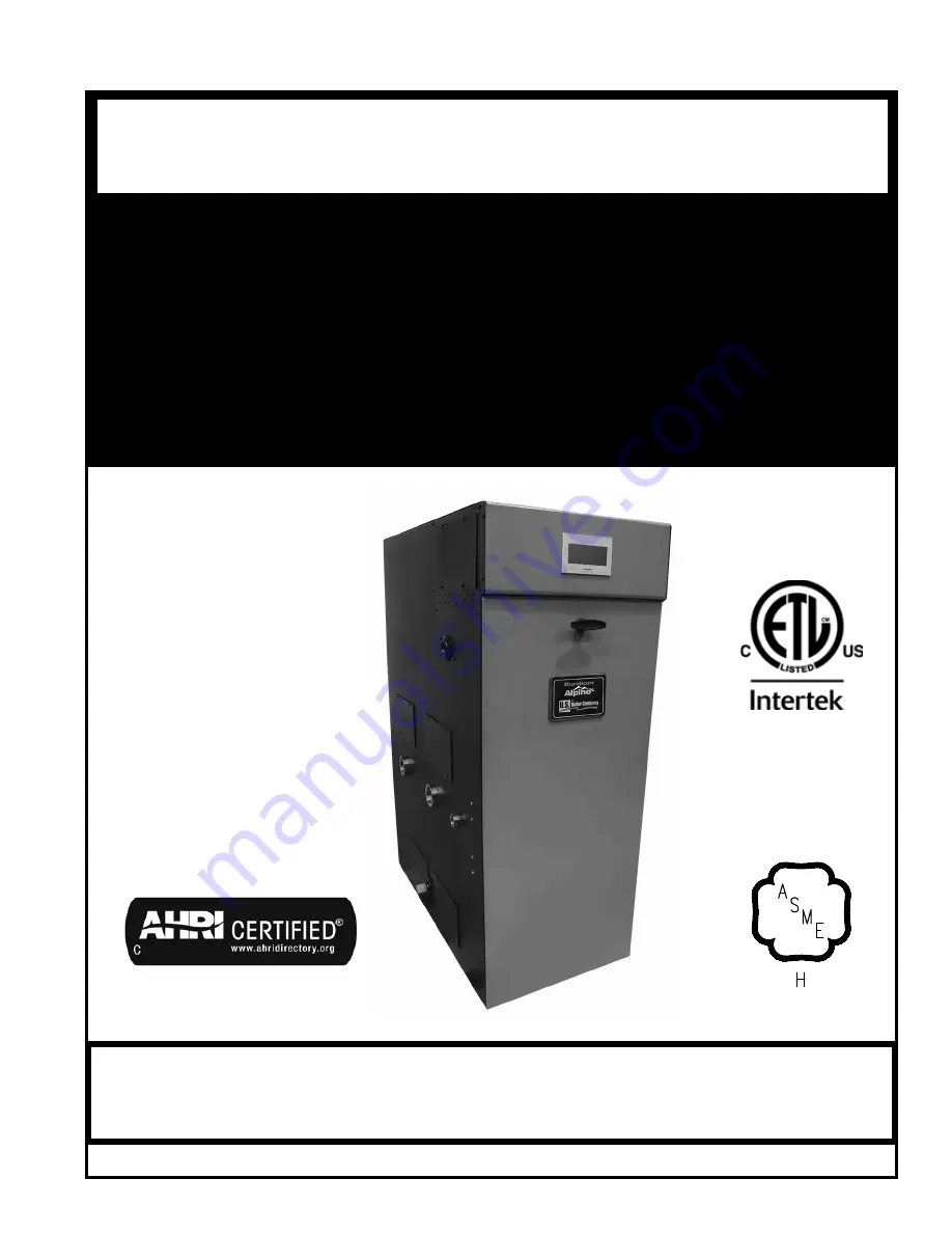
U.S. Boiler Company Alpine ALP500C Installation, Operating And Service Instructions Download Page 1

1

106307-02 - 2/17

Price - $5.00

Warning:

 Improper installation, adjustment, alteration, service or maintenance can cause property damage, 

injury, or loss of life. For assistance or additional information, consult a qualified installer, service agency  or  the 

gas supplier. This boiler requires a special venting system. Read these instructions carefully before installing.

inSTaLLaTiOn, OPEraTing anD

SErViCE inSTrUCTiOnS FOr

aLPinE

COnDEnSing HigH EFFiCiEnCY

DirECT VEnT

GAS - FIRED HOT WATER BOILER

Size range - 399 MBH through 800 MBH

9700609

   alpine “C” Models:

•  ALP399C

•  ALP500C

•  ALP600C

•  ALP700C

•  ALP800C

http://waterheatertimer.org/Two-water-heaters.html#boiler

http://waterheatertimer.org/What-size-indirect-heater.html

Summary of Contents for Alpine ALP500C

Page 1: ...gas supplier This boiler requires a special venting system Read these instructions carefully before installing INSTALLATION OPERATING AND SERVICE INSTRUCTIONS FOR ALPINE CONDENSING HIGH EFFICIENCY DIRECT VENT GAS FIRED HOT WATER BOILER Size Range 399 MBH through 800 MBH 9700609 Alpine C Models ALP399C ALP500C ALP600C ALP700C ALP800C http waterheatertimer org Two water heaters html boiler http wate...

Page 2: ...ates an imminently hazardous situation which if not avoided will result in death serious injury or substantial property damage CAUTION Indicates a potentially hazardous situation which if not avoided may result in moderate or minor injury or property damage WARNING Indicates a potentially hazardous situation which if not avoided could result in death serious injury or substantial property damage N...

Page 3: ...ll be permanently mounted to the exterior of the building at a minimum height of eight 8 feet above grade directly in line with the exhaust vent terminal for the horizontally vented gas fueled heating appliance or equipment The sign shall read in print size no less than one half 1 2 inch in size GAS VENT DIRECTLY BELOW KEEP CLEAR OF ALL OBSTRUCTIONS 4 A final inspection by the state or local gas i...

Page 4: ... Piping 54 VIII Electrical 59 IX System Start Up 71 X Operation 79 A Overview 79 B Supply Water Temperature Regulation 80 C Boiler Protection Features 81 D Multiple Boiler Control Sequencer 82 E Boiler Sequence of Operation 84 1 Normal Operation 84 2 Using the Display 85 3 Status Screens 86 4 Detail Screens 88 5 Multiple Boiler Sequencer Screens 89 F ChangingAdjustable Parameters 90 1 Entering Adj...

Page 5: ...ed for LP Gas no Field Conversion Max Allowable Water Temperature F 210 210 210 210 210 Max Allowable Working Pressure psi 160 160 160 160 160 Factory Supplied Safety Relief Valve psi 50 50 60 60 60 Boiler Water Volume gal 3 4 4 3 5 4 5 4 6 2 Heat Transfer Area sq ft 41 8 58 1 76 2 76 2 87 0 Approx Shipping Weight lb 316 368 458 458 500 Optional 80 psi and 100 psi safety relief valves are availabl...

Page 6: ... 1 2 5 5 16 E A 7 13 16 11 16 1 1 4 12 1 2 4 CPVC PP SS VENT CONNECTOR LINE VOLTAGE KNOCKOUTS 120 VOLTS LOW VOLTAGE KNOCKOUTS 24 VOLTS ACCESS PANEL ACCESS PANEL ACCESS PANEL ACCESS PANEL ACCESS PANEL H 1 1 2 FPT RETURN TAPPING J 1 1 2 FPT SUPPLY TAPPING G GAS VALVE INLET K CONDENSATE DRAIN 4 PVC COMBUSTION AIR CONNECTOR 3 4 FPT RELIEF DRAIN TAPPING ...

Page 7: ...12 3 8 8 5 16 5 3 8 C E D A 8 1 8 2 9 16 5 1 2 1 1 4 15 1 2 4 CPVC PP SS VENT CONNECTOR H 2 MPT RETURN TAPPING J 2 MPT SUPPLY TAPPING K CONDENSATE DRAIN G GAS VALVE INLET LINE VOLTAGE KNOCKOUTS 120 VOLTS LOW VOLTAGE KNOCKOUTS 24 VOLTS ACCESS PANEL ACCESS PANEL ACCESS PANEL ACCESS PANEL ACCESS PANEL 4 PVC COMBUSTION AIR CONNECTOR ...

Page 8: ... 10 5 16 20 5 16 8 1 8 6 7 8 C E D A 2 9 16 7 1 16 8 5 16 1 1 4 15 9 16 ACCESS PANEL ACCESS PANEL ACCESS PANEL ACCESS PANEL H 2 MPT RETURN TAPPING J 2 MPT SUPPLY TAPPING G GAS VALVE INLET K CONDENSATE DRAIN 6 CPVC PP SS VENT CONNECTOR LINE VOLTAGE KNOCKOUTS 120 VOLTS LOW VOLTAGE KNOCKOUTS 24 VOLTS ACCESS PANEL 4 PVC COMBUSTION AIR CONNECTOR ...

Page 9: ...Thermal Efficiency Combustion Efficiency Min Max ALP399C 80 399 375 326 94 1 94 5 ALP500C 100 500 485 422 97 0 96 0 ALP600C 125 625 594 517 95 0 96 0 ALP700C 145 725 689 599 95 0 95 0 ALP800C 160 800 760 661 95 0 94 0 Ratings shown are for installations at sea level and elevations up to 2000 ft at minimum vent length For elevations above 2000 ft see Appendix A Instructions for High Altitude Instal...

Page 10: ...mmended service clearance is 24 in 610 mm from left side front top and rear of the boiler Recommended front clearance may be reduced to the combustible material clearance providing 1 Access to boiler front is provided through a door or removable front access panel 2 Access is provided to the condensate trap located underneath the heat exchanger 3 Access is provided to thermal link located at boile...

Page 11: ...0 in 250 mm Right Side 2 in 50 mm Rear 6 in 150 mm Models ALP600C ALP700C and ALP800C These boilers are listed for alcove installation with the following minimum clearances Top 1 in 25 mm Front Open Left Side 10 in 250 mm Right Side 2 in 50 mm Rear 6 in 150 mm Note When boiler is vented vertically the minimum clearance from the rear of the jacket is increased to 18 in 460 mm with a short radius 90...

Page 12: ...ler model as bottom boiler b Each Alpine boiler is factory packaged with 2 stacking boiler attachment brackets P N 101679 01 and the bracket mounting hardware six 6 self drilling hex washer head plated 8 x long screws P N 80860743 Locate and remove the brackets and the hardware The stacking boiler attachment bracket has three 7 32 diameter holes punched in a triangular pattern See Figure 5 Boiler ...

Page 13: ...tally and 3 ft 900 mm vertically from each other in order to prevent combustion air contamination For vertical through the roof venting individual vertical vent terminals if level with each other must be spaced no closer than 12 in 300 mm horizontally If vertical terminals cannot end in one plane they must be spaced no closer than 3 ft 900 mm horizontally Follow instructions in Section IV Venting ...

Page 14: ...14 III Pre Installation and Boiler Mounting H Boiler Stacking continued Figure 5 Boiler Stacking ...

Page 15: ...Alpine may be installed as a direct vent sealed combustion boiler or with optional room air for combustion Direct vent is recommended for residential applications For direct vent pipe combustion air from the outdoors directly to the boiler cabinet Room air is optional for commercial applications For room air provide combustion and ventilation air per the National Fuel Gas Code ANSI Z223 1 or in Ca...

Page 16: ... 7 8 17 18 A C Vent Horizontal Sidewall UV Resistant Straight Pipe w Screen 8 Intake Horizontal Sidewall Ipex Low Profile 9 13 17 18 Vent Horizontal Sidewall 9 Intake Horizontal Sidewall UV Resistant 90 Elbow w Screen 7 8 10 17 18 Vent Vertical Roof UV Resistant Straight Pipe w Screen 10 Intake Vertical Roof 2 UV Resistant 90 Elbows w Screen 10 17 18 Vent Vertical Roof UV Resistant Straight Pipe w...

Page 17: ... in 80 mm 4 in 100 or 110 mm 6 in 150 or 160 mm 90 Elbow Short Radius 10 ft 3 0 m 13 ft 4 0 m 22 ft 6 7 m 90 Elbow Long Sweep Sanitary 4 0 ft 1 2 m 9 ft 2 7 m 17 ft 5 2 m 45 Elbow 3 0 ft 0 9 m 4 5 ft 1 4 m 7 5 ft 2 3 m Table 9 Vent System and Combustion Air System Component Equivalent Length Applies to All Listed Vent Combustion Air System Options Table 10 Vent and Combustion Air Equivalent Length...

Page 18: ...General Guidelines continued Figure 6 Location of Vent Terminal Relative to Windows Doors Grades Overhangs Meters and Forced Air Inlets Two Pipe System Vent Terminal Shown Two Pipe System Air Intake Terminal Not Shown ...

Page 19: ...not penetrate any part of the vent system with fasteners Les instructions d installation du système d évacuation doivent préciser que les sections horizontales doivent être supportées pour prévenir le fléchissement Les méthodes et les Figure 7 Direct Vent Sidewall Standard Terminations intervalles de support doivent être spécifiés Les instructions divent aussi indiquer les renseignements suivants ...

Page 20: ...ing is recommended ii If possible locate vent and combustion air terminals on the same wall to prevent nuisance shutdowns If not boiler may be installed with roof vent terminal and sidewall combustion air terminal iii When installed on the same wall locate vent terminal at same height or higher than combustion air terminal c Locate bottom of vent and combustion air terminals at least 12 in 300 mm ...

Page 21: ...d by the authority having jurisdiction and local experience the terminal may be located closer to unventilated soffits The minimum vertical separation depends upon the depth of the soffit See Figure 6 for details l Maintain minimum 12 in 300 mm horizontal spacing between vent terminal and a building corner m Under certain conditions water in the flue gas may condense and possibly freeze on objects...

Page 22: ...ed for optional vertical roof terminals shown in Figure 10 2 Field Installation of CPVC PP SS Vent Connector Refer to Figure 12 and following steps a Position the vent connector and gasket onto boiler rear panel and insert vent connector into heat exchanger vent outlet b Align vent connector plate and gasket clearance holes with rear panel engagement holes Be sure combustion sample port is on left...

Page 23: ...nal Horizontal Snorkel Termination Table 13 Components Required for Optional Ipex Low Profile Sidewall Termination Description Ipex Part Number U S Boiler Company Part Number Applicable to Boiler Sizes 3 in Low Profile Termination Kit 196985 106415 03 399 reduced dia 500 reduced dia 4 in Low Profile termination Kit 196986 106415 04 399 standard dia 500 standard dia 600 reduced dia 700 reduced dia ...

Page 24: ... Table 15 c All CPVC PVC vent and combustion air pipe joints must be cleaned with primer and glued with cement Follow all manufacturer instructions and warnings when preparing pipe ends for joining and using the primer and the cement 5 Horizontal Sidewall Termination a Standard Two Pipe Termination See Figure 7 i Vent Piping Running PVC vent pipe inside Enclosures and through Walls PVC vent pipe m...

Page 25: ...Wall Penetration Clearances for PVC Vent Pipe Wall thimbles for CPVC PVC pipe are available from U S Boiler Company P N s 102180 01 3 in 102181 01 4 in 103419 01 6 in Apply sealant between vent pipe and wall opening to provide weather tight seal Sealant should not restrain the expansion of the vent pipe Install contractor provided optional trim plate on wall outside surface to cover wall opening s...

Page 26: ...iping if required ii Combustion Air Piping After penetrating wall install a Schedule 40 PVC 90 elbow so that elbow leg is in the up direction Install maximum vertical run of 7 ft 2 1 m of Schedule 40 PVC vent pipe See Figure 8 At top of air pipe length install another PVC 90 elbow so that elbow leg is opposite the building s exterior surface Install screen and combustion air terminal supplied with...

Page 27: ...der A General Guidelines of this section WARNING AsphyxiationHazard Followtheseinstructions and the installation instructions included by the listed polypropylene venting component manufacturers whichever applicable Failure todosocouldcauseproductsofcombustionto enter the building resulting in severe property damage personal injury or death Where a conflict arises between a manufacturer s instruct...

Page 28: ...ly de burred prior to assembly Use locking band clamps at all vent pipe joints a Plan venting system to avoid possible contact with plumbing or electrical wires Start at vent connector at boiler and work towards vent termination b Follow all manufacturer instructions and warnings when preparing pipe ends for joining and when assembling the vent combustion air system c Use locking band clamps at al...

Page 29: ...lypropylene Vent Combustion Air System Components Table 17B Listed Polypropylene Pipe Fittings and Terminations Centrotherm Eco Boiler Model Nominal Pipe Diameter Pipe Joint Locking Band Clamp Combustion Air Vent Ipex Low Profile Adapter Kit Pipe Adapter Wall Plate Boiler Adapter Sidewall Termination UV Resistant 90 Elbow w Screen Roof Termination 2 UV Resistant 90 Elbows w Screen Boiler Adapter S...

Page 30: ...zontal position g Follow flexible polypropylene pipe liner manufacturer specific installation instructions regarding application listing permits minimum clearances to combustibles installation details proper joint assembly pipe support and routing gasket and fitting installation optional tooling availability usage routing through masonry Boiler Model Nominal Pipe Diameter Pipe Joint Locking Band C...

Page 31: ...ation of combustion product venting and combustion air supply h When there is a conflict between flexible polypropylene pipe liner manufacturer installation instructions and Alpine boiler Installation Operating and Service Instructions the more restrictive instructions shall govern Figure 19 Locking Band Clamp Installation M G DuraVent or Centrotherm InnoFlue Figure 20 Alternate Locking Band Clamp...

Page 32: ...IV Venting C Polypropylene Venting continued Figure 21 Flexible Vent in Masonry Chimney with Separate Combustion Air Intake Venting of Other Appliances or Fireplace into Chase or Adjacent Flues Prohibited ...

Page 33: ... as GE RTV102 Seal PVC combustion air piping sections with PVC cement d Do not drill holes in vent pipe 2 Field Installation of Stainless Steel Vent Adapter see Figure 22 a No adapter is required for stainless steel vent pipe unless vent diameter is reduced per Table 8 See Table 19 20 or 21 for adapters for reduced vent diameter Table 19 U S Boiler Company Heat Fab Vent System Components Stainless...

Page 34: ...VSR0403 2SVSTPX03 2SVSWTF03 ALP399C standard dia ALP500C standard dia ALP600C reduced dia vent ALP700C reduced dia vent ALP800C reduced dia vent 4 in 100 mm ALP399C ALP500C No Adapter Re quired ALP600C ALP700C ALP800C 2SVSR0604 2SVSTPX04 2SVSWTF04 ALP600C standard dia vent ALP700C standard dia vent ALP800C standard dia vent 6 in 150 mm No Adapter Required 2SVSTPX06 2SVSWTF06 Note When using room a...

Page 35: ...building s exterior surface Install horizontal vent terminal Brace exterior piping if required ii Combustion Air Termination After penetrating wall install a 90 elbow so that the elbow leg is in the up direction Install maximum vertical run of 7 ft 2 1 m of combustion air pipe as shown in Figure 8 At top of vent pipe length install another 90 elbow so that the elbow leg is opposite the building s ...

Page 36: ... Auto Reset External Limit connections See Section VIII Electrical 3 Terminations a For standard horizontal sidewall terminations see Figures 7 and 8 When using room air for combustion use 90 elbow or tee for sidewall vent termination NOTICE Use 90 elbow or tee for horizontal sidewall vent termination when using room air for combustion b For vertical roof terminations see Figures 10 and 11 F Remov...

Page 37: ...rette d un cigare ou d une pipe 6 Une fois qu il a été déterminé selon la méthode indiquée ci dessus que chaque appareil raccordé au système d évacuation est mis à l air libre de façon adéquate Remettre les portes et les fenêtres les ventilateurs les registres de cheminées et les appareils au gaz à leur position originale 7 Tout mauvais fonctionnement du système d évacuation commun devrat être cor...

Page 38: ...gure 23 IV Venting G Multiple Boiler Installation Venting continued b Each individual boiler must have own combustion air pipe and terminal Refer to Paragraphs A through F as applicable for individual boiler combustion air guidelines and options c Do not exceed the individual boiler maximum combustion air pipe length listed in Table 8 d If possible locate vent and combustion air terminals for an i...

Page 39: ...39 Figure 23 Multiple Boiler Direct Vent Termination IV Venting G Multiple Boiler Installation Venting continued ...

Page 40: ... located at boiler left side below inlet and outlet water pipe connections Refer to Figures 1 2 3 and 24 5 Condensate trap must be filled up with water prior to boiler start up and before connecting any condensate line to the boiler to insure combustion products cannot escape from operating boiler To fill the trap inject water in the amount of 1 cup 240ml through condensate trap connection Do not ...

Page 41: ...odes and instructions enclosed with the kit for condensate neutralizer installation 3 Limestone chips will get coated by neutral salts product of chemical reaction between limestone and acidic condensate and lose neutralizing effectiveness over time Therefore periodic condensate neutralizer maintenance and limestone chip replacement must be performed A pH test or acid test kits are available from ...

Page 42: ...d service circulator replacement etc Oxygen contamination of boiler water will cause corrosion of iron and steel boiler components and can lead to boiler failure U S Boiler Company s Standard Warranty does not cover problems caused by oxygen contamination of boiler water or scale lime build up caused by frequent addition of water Do not fill boiler with softened water to prevent chloride contamina...

Page 43: ...ne boilers are designed to operate in a closed loop pressurized system Minimum pressure in the boiler must be 14 5 psi 100 kPa Proper operation of the Alpine boiler requires that the water flow through the boiler remain within the limits shown in Table 24 any time the boiler is firing NOTICE Failure to maintain the flow through boiler within specified limits could result in erratic operation or pr...

Page 44: ... 80 2 Spd 3 Table 25 Recommended Taco Circulators for 50 ft Equivalent ft Near Boiler Piping Approximately 20 ft Straight Pipe 4 90 Elbows and 2 Full Port Ball Valves Boiler Model Supply Return Connection in Near Boiler Pipe Size in DT 35 F DT 30 F DT 25 F DT 20 F Flow GPM Boiler Piping Head Loss ft Circulator Model Flow GPM Boiler Piping Head Loss ft Circulator Model Flow GPM Boiler Piping Head L...

Page 45: ...he replacement safety relief valve Pipe the safety relief valve discharge to a location where hot water or steam will not create hazard or property damage if the valve opens The end of the discharge pipe must terminate in an unthreaded pipe If the safety relief valve is not piped to a drain it must terminate at least 6 in 150 mm above the floor Do not run safety relief valve discharge piping throu...

Page 46: ...air during initial fill 7 Manual Reset High Limit Alpine boilers have factory provided UL353 listed boiler control and UL1434 listed manual reset high limit An optional manual reset external high limit is available from U S Boiler Company to meet local code requirements 8 Y strainer Recommended A Y strainer or equivalent strainer removes heating system debris from hydronic systems and protects boi...

Page 47: ...ubject to the effects of corrosion Failure to take the following precautions to minimize corrosion and heat exchanger waterways overheating could result in severe boiler damage Before connecting the boiler insure the system is free of impurities grease sediment construction dust sand copper dust flux and any residual boiler water additives Flush the system thoroughly and repeatedly if needed with ...

Page 48: ...48 VI Water Piping and Trim continued Figure 28 Near Boiler Piping Heating Only ...

Page 49: ... Water Heater VI Water Piping and Trim continued NOTICE For single boiler servicing indirect water heater IWH install DHW sensor at boiler side inlet to IWH Header Sensor cannot be used to control modulation for DHW demand on a single boiler installation ...

Page 50: ...All components on the oxygenated side of the heat exchanger such as the pump and expansion tank must be designed for use in oxygenated water VI Water Piping and Trim continued 2 Piping with a Chiller If the boiler is used in conjunction with a chiller pipe the boiler and chiller in parallel Use isolation valves to prevent chilled water from entering the boiler 3 Boiler Piping with Air Handlers Whe...

Page 51: ...o Section VIII Electrical and Section X Operation 3 For installations where indirect domestic hot water heater is combined with space heating the Alliance SL model must be piped as a separate heating zone off the system header The circulator must be sized based on the Alliance SL model coil flow and combined coil pressure drop and the zone piping total equivalent length Refer to Alliance SL Indire...

Page 52: ...er Water Piping w Domestic Hot Water Heater Page 1 of 2 VI Water Piping and Trim continued NOTICE Installing a low water cutoff in the system piping of multiple boilers is strongly recommended and may be required by local codes ...

Page 53: ... Boiler Water Piping w Domestic Hot Water Heater Page 2 of 2 VI Water Piping and Trim continued NOTICE Installing a low water cutoff in the system piping of multiple boilers is strongly recommended and may be required by local codes ...

Page 54: ...allowable system pressure is psig 3 4 kPa Actual point of delivery pressure may be less contact gas supplier for additional information Minimum gas valve inlet pressure is printed on the rating label located in the boiler s vestibule compartment 2 Maximum gas demand Refer to the boiler s input as printed on its rating label Also consider existing and expected future gas utilization equipment i e w...

Page 55: ...1239 3 3 068 7615 5234 4203 3597 3188 2889 2658 2472 2320 2191 1 CFH of LP Gas is approximately equal to 2 5 MBH contact your gas supplier for the actual heating value of your gas Table 31 Equivalent Lengths of Standard Pipe Fittings Valves ft Nominal Pipe Size Inc Inside Diameter In Valves Screwed Fully Open Screwed Fittings Gate Globe Angle Swing Check 45 Elbow 90 Elbow 180 Close Return Bend 90 ...

Page 56: ...e of such requirements follow National Fuel Gas Code ANSI Z223 1 NFPA 54 and or Natural Gas and Propane Installation Code CAN CSA B149 1 2 Use thread joint compounds pipe dope resistant to action of liquefied petroleum gas 3 Alpine boilers have factory supplied miscellaneous parts cartons which include gas piping components to connect boiler gas valve s to gas supply system Install these component...

Page 57: ...s open flames or other ignition source to check for leaks D Alpine Models ALP500C ALP600C ALP700C ALP800C if equipped with optional low and high gas pressure switches 1 Verify low and high gas pressure switch settings are within the range shown in kit instructions The switches are preset for natural gas For LP gas the low gas pressure switch setting must be adjusted 2 The low gas pressure switch m...

Page 58: ...at the smallest individual module boiler CAUTION If gas pressure in the building is above psig 3 4 kPa an additional gas pressure regulator is required Using one additional regulator for multiple boilers may result in unsafe boiler operation The additional regulator must be able to properly regulate gas pressure at the input of the smallest boiler If the regulator cannot do this two or more additi...

Page 59: ...lectrical Code NFPA 70 and or Canadian Electrical Code Part 1 CSA C22 1 Electrical Code Provide over current protection not greater than 15A B A separate electrical circuit must be run from the main electrical service with an over current device disconnect in the circuit A service switch is recommended and may be required by some local jurisdictions Install the service switch in the line voltage H...

Page 60: ...60 Figure 37 PCB Locations for Field Wiring Figure 38 120 VAC Field Wiring VIII Electrical continued ...

Page 61: ...up direct radiation from the sun should also be avoided Avoid placing the sensor near potential sources of electrical noise such as transformers power lines and fluorescent lighting Wire the sensor to the boiler using 22 gauge or larger wire As with the sensor the sensor wiring should be routed away from sources of electrical noise Where it is impossible to avoid such noise sources wire the sensor...

Page 62: ...62 Figure 40 Ladder Diagram VIII Electrical continued ...

Page 63: ...63 VIII Electrical continued 2 Figure 41 Wiring Connections Diagram ...

Page 64: ...II Electrical continued Figure 42 Modified Wiring For DHW Priority When Using Low Flow Circulator Piped Off System Header Heating with Central Heating Circulators Plus Alternately Piped Indirect Water Heater ...

Page 65: ...gure 43 Modified Wiring For DHW Priority When Using Low Flow Circulator Piped Off System Header Heating with Central Heating Zone Valves Plus Alternately Piped Indirect Water Heater VIII Electrical continued ...

Page 66: ...66 Figure 44 Multiple Boiler Wiring Diagram Internal Multiple Boiler Control Sequencer Two Boilers Shown Typical Connections for up to Eight Boilers VIII Electrical continued ...

Page 67: ...67 VIII Electrical continued Figure 45 Boiler to Boiler Communication with Zone Control Circulator Panel ...

Page 68: ...ween the Tekmar 265 Control and each boiler s control The boiler s and system supply water temperature will be reset together to maintain the input that is needed to the system When a call for Indirect Hot Water is generated to the Tekmar 265 the control will de energize the zone pump control ZC terminal energize the Indirect pump and modulate the boiler firing to establish a setpoint temperature ...

Page 69: ...perature to supply enough input to the system main to satisfy the desired reset water temperature in the main established by the Tekmar 264 Control When a call for Indirect Hot Water is generated to the Tekmar 264 the control will de energize the zone pump control ZC terminal energize the Indirect pump and sequentially fire the boilers to establish a setpoint temperature in the main for the Indire...

Page 70: ...ended temperature information to the Sequence Master Refer to Figure 34 for installation location and Figure 32 or 33 for installation detail b Ethernet Cables Ethernet cables are used to connect the boiler network together These are standard straight through cables that can be purchased at electrical distributors Alternately the network can be wired together by simply wiring Modbus Boiler to Boil...

Page 71: ...imum allowable working pressure on the heat exchanger ASME plate IX System Start up E Confirm that the boiler and system have no water leaks NOTICE If it is required to perform a long term pressure test of the hydronic system the boiler should first be isolated to avoid a pressure loss due to the escape of air trapped in the boiler To perform a long term pressure test including the boiler ALL trap...

Page 72: ...72 IX System Start up continued Figure 48 Operating Instructions ...

Page 73: ...could result in property damage personal injury or loss of life WARNING Any gas valve adjustments throttle and or offset specified herein and subsequent combustion data O2 CO2 CO air free ppm collection must be performed using a calibrated combustion analyzer Failure to use combustion analyzer could result in property damage personal injury or loss of life 1 Use a combustion analyzer to sample boi...

Page 74: ...ttle screw clockwise in 1 4 turn increments and checking the O2 or CO2 after each adjustment If boiler is equipped with 2 gas valves throttle screw adjustments must be done to both gas valves equally and simultaneously Refer to Figure 50 for location of throttle screw Verify CO air free is less than 200 ppm c If high fire O2 is too high CO2 is too low decrease O2 increase CO2 by turning the thrott...

Page 75: ...ld be performed by a qualified service agency in accordance with the manufacturer s instructions and all applicable codes and requirements of the authority having jurisdiction If the information in these instructions is not followed exactly a fire an explosion or production of carbon monoxide may result causing property damage personal injury or loss of life The qualified service agency is respons...

Page 76: ...uous surface on or adjacent to the outer boiler jacket Fill in the date of the conversion and the name and address of the company making the conversion with a permanent marker U Correcting Throttle Screw Mis Adjustment if required Alpine boilers are fire tested at factory and gas valve throttle screws are preset However if boiler does not start when first turned on and the problem cannot be remedi...

Page 77: ...ion Parameter Description 1 120V PCB 120V Line Is line voltage connected with overcurrent protection Boiler System and DHW Pumps Confirm pumps are connected If using room air for combustion confirm combustion air damper is connected 2 Low Voltage Connections PCB Enable Disable Is the space heating thermostat connected Ensure thermostat is a dry non powered input DHW Demand Is an indirect water hea...

Page 78: ...ater temperature Setpoint is correct for your type of radiation 6 Adjust Domestic Hot Water Setpoint Ensure target domestic hot water temperature Setpoint is correct DHW Modulation Sensor If using DHW Sensor select DHW Sensor 7 Adjust Outdoor Reset Central Heat Enable Disable If not using an outdoor sensor select Disable 8 Adjust Sequencer Master Sequencer Master If boiler is the master boiler in ...

Page 79: ...omer fuel dollars pre and post purge sends heat up stack and saves wear and tear on the boiler Lowering the boiler s firing rate saves fuel dollars by increasingtheamountoffluegascondensation always the goal of condensing boiler installations 5 Built in Safety Control TheControlincludessafetycontrolsdesignedtoensure safe and reliable operation In addition to flame safety controlstheControlincludes...

Page 80: ...utdoor Air Reset 5 Outdoor Air Reset If an outdoor temperature sensor is connected to the boiler and Outdoor Reset is enabled the Central Heat andAuxiliaryHeatsetpointswillautomaticallyadjusted downwards as the outdoor temperature increases When the water temperature is properly matched to heating needs there is minimal chance of room air temperatureovershoot Excessiveheatisnotsenttothe room heati...

Page 81: ...tries five times then soft lockout for one hour Size 500 800 retries one time then manual reset hard lockout 7 Automatic Reset Limit Devices If any below listed limit opens the boiler shuts down and provides an open limit indication The boiler will automatically restart once the limit closes An external limit control with its own manual reset button requires pressing external limit reset button af...

Page 82: ... be setup to automatically resume control as a stand alone boiler c Slave Boiler Rate Adjustment Each slave boiler continues to monitor supply return and flue gas temperatures and modifies the Sequence Master s firing rate demand to help avoid individual boiler faults minimize boiler cycling and provide heat to the building efficiently d SlaveBoilerStatusMonitoring TheSequenceMaster monitorsslaveb...

Page 83: ... gas water vapor condensation The Control maintains a Base Load Common Rate until the last lag boiler is started At this point the Base Load Common Rate is released to allow boilers to modulated as required to meet heat load X Operation D Multiple Boiler Control Sequencer continued 11 Advanced Boiler Sequencing After there is a Call For Heat input both header water temperatureandboilerfiringratepe...

Page 84: ...ning Priority Central Heat Status Running burner On circulator s On After flame is proven the sequence continues with run stabilization and low fire hold time Once the field adjustable low fire hold time is completed normal boiler operation begins modulation rate depending on temperature and setpoint selections Priority Domestic Hot Water Status Running If the Central Heat call for heat is active ...

Page 85: ...ation Menu Buttons The Home Screen Menu Buttons connect the displays four main display groups Information Symbol Information symbol links most screens to screen content explanations New terminology used in status and adjustment screens are explained in plain words Fault Indication In the event of a boiler fault the screen color turns red and the user is guided by blinking touch buttons to Help scr...

Page 86: ...quirements When a rate limit is the result of boiler protection logic the 6 symbol blinks and becomes a screen link Rate The rate value is equal to the actual kbtu hr input divided by the boiler rated input Priority The selected Priority is shown Available Priorities are Standby no call for heat is present Sequencer Control Central Heat Auxiliary Heat Domestic Hot Water Frost Protection or Warm We...

Page 87: ...ads can be an indication of gas supply issues Additionally supply and return tempera ture dual pen trends brings a focused look at heat exchanger and pump performance For example studying a differential temperature trend may indicate pump speed settings need to be changed Trend Screens NOTE Firing Rate Trend shows fan demand and feedback Burner Status Screen Cycles and Hours Boiler cycles and hour...

Page 88: ...ore Press the zone control button to view individual zone Zone Panel 1 typical for 2 through 4 Zone panel screens show individual zone status cycle counts and individual zone heat loss size in kbtu hr Individual zone heat loss may be adjusted under the Adjust Modulation menu Also zone descriptions may be modified using the Zone Control Description Setup menu Detail screens are accessed by selectin...

Page 89: ...cer Priority is shown Available Priorities are Standby no call for heat is present Central Heat Auxiliary Heat Domestic Hot Water Frost Protection or Warm Weather Shutdown Sequence Status Slave boiler status is provide as follows Available Add Stage Running On Leave Recovering Disabled Boiler is ready and waiting to be started by the Sequencer Master Boiler has begun the start sequence but has not...

Page 90: ...on the Home screen Press the Adjust button on the Adjust Mode screen or Press Service Contact for service provider contact information Press Login button to access password screen Press 5 digit display to open a keypad Enter the password Installer Password is 86 and press the return arrow to close the keypad Press the Save button Press the Adjust button to enter Adjustment mode F Changing Adjustab...

Page 91: ...ted Connected Not Connected Zone Control Status Connected When the Zone Control is connected adjustable settings are automatically shown under the Adjust Modulation Auxiliary Heat and Zone Control Description Setup menus This feature allows these adjustments to be made before the zone panel is connected When the user selects Show As If Connected Zone Control related parameters are made visible and...

Page 92: ...ng Range Choices Parameter and Description Varies by Model See Figure 56 Boiler Type Boiler Size Setup To verify the boiler size selection a qualified technician should do the following 1 Check boiler s label for actual boiler size 2 Set Boiler Type to match actual boiler size 3 Select Confirm The Boiler Type parameter changes the minimum and maximum modulation settings This param eter is intended...

Page 93: ...eat Rate Adjustment Screens HeatMatch Software Figure 57 Four Zone House with Zone Control Connected Maximum Heat Rate Automatically adjusted by the Control based on the size and number of zones calling for heat Example call for heat durations for a four zone house Maximum heat rate limits firing rate and prevents the Control from firing to 100 in response to a smaller zone demands Actual Heat Rat...

Page 94: ...ed Heat Rate This parameter defines the highest modulation rate the Control will go to during the auxiliary heat call for heat If the rated input of the Auxiliary Heat Zones is less than the maximum output of the boiler change the Auxiliary Heat Maximum Expected Heat Rate fan speed setting to limit the boiler output accordingly 40 Minimum to Maximum Heat Rate Zone 1 Expected Heat Rate typical for ...

Page 95: ... Pump runs during central heat and frost protection call for Off DHW demand heat Pump does not start for a DHW call for heat and will be forced off if there is a DHW call for heat and Domestic Hot Water Priority is active Header Sensor Demand Pump runs when boiler is firing to satisfy any call for heat Combustion Air Damper Used when header sensor is enabled to prevent unnecessary operation of boi...

Page 96: ...at Domestic hot water priority is optional It is permissible for the domestic and system pumps to run at the same time The boiler pump must run for every call for heat Example Pump Parameter selections continued Single boiler Primary Piped Indirect Water Heater Optional DHW Priority Single boiler with no Indirect Water Heater Explanation This piping arrangement only services central heat When ther...

Page 97: ...ugh boiler within limits shown in Table 12 This piping arrangement does not allow both the Slave 1 s boiler and domestic hot water pump to run at the same time When call for Domestic Hot Water is received the DHW pump is turned on and the boiler pump is turned off However the system pumps may run to satisfy a central heat demand that is being satisfied by a different slave The central heat demand ...

Page 98: ...le for the domestic and system pumps to run at the same time The boiler pump must run for every call for heat Example Pump Parameter selections continued Multiple Boilers Primary Piped Indirect Water Heater Optional DHW Priority Multiple Boilers Primary Piped Indirect Water Heater System Pump Run for Any Demand Sequencer Master Boiler 1 Boiler 2 Wiring locations Enable Disable X DHW Demand X Syste...

Page 99: ...ter Contractor Information Bill Smith Press SAVE button to store revisions For Service Contact Bill Smith 12 Victory Lane Plainview New York 516 123 4567 Example Screen Press Manual Control button to access the following screen The Manual Speed Control speed screen allows the technician to set firing rate at low or high speed for combustion testing NOTE Selecting Low or High locks manual mode firi...

Page 100: ... the water temperature drops Diff Below degrees below the setpoint 3 1 to 5 Response Speed This parameter adjusts the Central Heat temperature controller Proportion Integral Derivative PID values Higher values cause a larger firing rate change for each degree of temperature change If set too high firing rate overshoots required value increases to high fire causing the temperature to exceed the Dif...

Page 101: ...rshoots required value increases to high fire causing the temperature to exceed the Diff Above setpoint and cycle the boiler unnecessarily Lower values cause a smaller firing rate change for each degree of temperature change If set too low the firing rate response will be sluggish and temperature will wander away from setpoint Disable Disable Enable Auxiliary Priority Over Central Heat This parame...

Page 102: ...ly Lower values cause a smaller firing rate change for each degree of temperature change If set too low the firing rate response will be sluggish and temperature will wander away from setpoint 10 seconds 0 to 1800 seconds Low Fire Hold Time Low Fire Hold Time is the number of seconds the control will wait at low fire modulation rate before being released to modulate After ignition and flame stabil...

Page 103: ...culation It is typically set to the coldest outdoor temperature 70 F 21 1 C 35 F to 100 F 1 7 C to 37 8 C Central Heat High Outdoor Temperature The High Outdoor Temperature parameter is the outdoor temperature at which the Low Boiler Water Temperature is supplied This parameter is typically set to the desired building temperature 110 F 43 3 C 70 F to 180 F 21 1 C to 82 2 C Central Heat Low Boiler ...

Page 104: ...to 0 C Auxiliary Heat Low Outdoor Temperature The Low Outdoor Temperature parameter is also called Outdoor Design Temperature This parameter is the outdoor temperature used in the heat loss calculation It is typically set to the coldest outdoor temperature 70 F 21 1 C 35 F to 100 F 1 7 C to 37 8 C Auxiliary Heat High Outdoor Temperature The High Outdoor Temperature parameter is the outdoor tempera...

Page 105: ... Fan Coil 100 F to 140 F 37 8 C to 60 C In Slab Radiant High Mass Radiant 160 F to 190 F 71 1 C to 87 8 C Convection Baseboard Fin Tube Convective 130 F to 160 F 54 4 C to 71 1 C Staple up Radiant Low Mass Radiant 130 F to 160 F 54 4 C to 71 1 C Radiant Baseboard 140 F to 160 F 60 C to 71 1 C Radiators Figure 59 Outdoor Reset Curve Typical for Central Heat and Auxiliary Heat ...

Page 106: ...d increases 70 25 100 Base Load Common Rate To maximize condensing boiler efficiency the firing rate is limited to an adjustable value Boilers are kept at or below this firing rate as long as the boilers can handle the load After last available boiler has started the modulation rate limit is released up to 100 3 0 5 Response Speed This parameter adjusts the Sequence Master temperature controller P...

Page 107: ...sed as the temperature setpoint The following two parameters may be used to adjust the signal range Modbus Modbus is used as the temperature setpoint 130 F 54 4 C 80 F 26 7 C Central Heat Setpoint Central Heat 4 20mAdc Setup 4 mA Water Temperature Sets the Central Heat Temperature Setpoint corresponding to 4mA for signal input terminals Current below 4mA is considered invalid failed or incorrect w...

Page 108: ...d Zone Control 1 Zone 3 Central Heat 4 User defined Zone Control 1 Zone 4 Central Heat 1 User defined Zone Control 2 Zone 1 Central Heat 2 User defined Zone Control 2 Zone 2 Central Heat 3 User defined Zone Control 2 Zone 3 Central Heat 4 User defined Zone Control 2 Zone 4 Central Heat 1 User defined Zone Control 3 Zone 1 Central Heat 2 User defined Zone Control 3 Zone 2 Central Heat 3 User define...

Page 109: ...d respirator 2 Long sleeved loose fitting clothing 3 Gloves 4 Eye Protection Take steps to assure adequate ventilation Wash all exposed body areas gently with soap and water after contact Wash work clothes separately from other laundry and rinse washing machine after use to avoid contaminating other clothes Discard used RCF components by sealing in an airtight plastic bag RCF and crystalline silic...

Page 110: ...talled on the heating system to prevent damage if the boiler is inoperative Burn Hazard This boiler contains very hot water under high pressure Do not unscrew any pipe fittings nor attempt to disconnect any components of this boiler without positively assuring the water is cool and has no pressure Always wear protective clothing and equipment when installing starting up or servicing this boiler to...

Page 111: ... boiler damage or malfunction if the following steps are not performed at the intervals specified A Continuously 1 Keep the area around the boiler free from combustible materials gasoline and other flammable vapors and liquids 2 Keep the area around the combustion air inlet terminal free from contaminates 3 Keep the boiler room ventilation openings open and unobstructed B Monthly Inspections 1 Ins...

Page 112: ...on inhibitor ii Fernox Protector Alphi 11 CH Copal sludge remover corrosion inhibitor CAUTION ATTENTION Electrical Shock Hazard Label all wires prior to disconnection when servicing controls Wiring errors can cause improper and dangerous operation Verify proper operation after servicing Au moment de l entretien des commandes étiquetez tous les fils avant de les débrancher Les erreurs de câblage pe...

Page 113: ...t U S Boiler Company for specific details ii Sentinel X500 Inhibited Antifreeze combined antifreeze and inhibitor Follow manufacturer application procedure to insure proper antifreeze concentration and inhibitor level Above referenced products are available from Douglas Products and Packaging 1550 E Old 210 Highway Liberty MO 64068 Tel 877 567 2560 Toll Free and or selected HVAC distributors b Equ...

Page 114: ...e trap see Section V Condensate Disposal and verify the switch operation 2 CondensateTrapRemovalandReinstallation a Disconnect power supply to boiler b Remove2wirenutsanddisconnectoverflowswitch wire pigtails from boiler wiring c Disconnect pressure switch hose from condensate trap d Disconnectoutsidecondensatecompressionfitting from condensate trap e Using pliers release spring clip securing the ...

Page 115: ...etails k Insure that pressure switch hose is reconnected to the trap l Restore power supply to boiler Fill up the trap see Section V Condensate Disposal and verify the switch operation F Control Compartment Access 1 Non stacked boiler installations Remove top front panel to access control compartment 2 Stacked boiler installations Remove front door and display panel As shown in Figure 62 remove tw...

Page 116: ... Help button from the Home screen When a fault is active the Help button flashes and the home screen turns a red color Continue to select flashing buttons to be directed to the Fault cause B Display Faults Figure 63 Help Menu Indication Condition Possible Cause Display Completely Dark Fan off LWCO lights off no green power light on Control No 120Vac Power at Boiler Check breaker and wiring between...

Page 117: ... disconnected Sequencer Master was Enabled and then Disabled Master s Boiler has been powered down To clear fault restore communication or cycle power Boiler Size Setup Boiler Size Fault WARNING Boiler size setting may not match actual boiler size The Boiler size setting determines min max and light off blower speeds Incorrect boiler size can cause hazardous burner conditions and improper operatio...

Page 118: ... Hard Lockout section for corrective actions High Stack Temperature Limit High Supply Temperature Limit High Differential Temperature Limit The following messages appear as part of normal start and stop sequences Minimum Modulation normal start stop sequence Low Fire Hold Rate Low fire hold rate is a normal start up rate hold used to help ensure system temperature feedback prior to release to modu...

Page 119: ...ure sensor wiring Defective flue temperature sensor 11 Ignition failure Model ALP399C flame failure after 5 tries to restart No gas pressure Gas pressure under minimum value shown on rating plate Gas line not completely purged of air Defective Electrode Loose burner ground connection Defective Ignition Cable Defective gas valve check for 24 Vac at harness during trial for ignition before replacing...

Page 120: ... pump not operating Boiler pump undersized Valve closed 18 Light off rate proving failed Blower is not running at Light off rate when it should or blower speed signal not being detected by Sage2 2 Loose connection in 120 VAC blower wiring Loose or miswired blower speed harness Defective blower 19 Purge rate proving failed Blower is not running at Purge rate when it should or blower speed signal no...

Page 121: ...terrupted Airflow Switch IAS ON Air proving switch failed to open Air proving switch closed before Prepurge Failed air proving switch Check switch for proper operation Short in limit string wiring 27 Interrupted Airflow Switch IAS OFF Air proving switch failed to close Air proving switch open during Prepurge or Drive Lightoff Check for vent or combustion air pipe blockage Confirm air proving switc...

Page 122: ...entatives or outlets Should you require assistance in locating a U S Boiler Company representative or outlet in your area or have questions regarding the availability of U S Boiler Company products or repair parts please contact U S Boiler Company Customer Service at 717 481 8400 or Fax 717 481 8408 SIZE 399 525 ONLY ...

Page 123: ...I 81660375 Alternate Safety Relief Valve Kit not shown includes safety relief valve and temperature and pressure gauge 80 PSI 104200 01 100 PSI 104201 01 1M Boiler Drain Valve 3 4 in NPT not shown 806603061 XIII Repair Parts continued Burner Components Key No Description Part Number ALP399C ALP500C ALP600C ALP700C ALP800C 1N Replacement Burner Kit includes burner burner gasket and hardware 104988 ...

Page 124: ...124 XIII Repair Parts continued ...

Page 125: ...ate and mounting hardware 104620 04 104620 05 2E Replacement Gas Valve Kit includes one gas valve and o rings 105004 01 105004 04 2F Gas Valve 90 Flange Kit includes one 90 flange o ring and hardware N A 102972 03 2G Gas Valve Wire Harness includes harness with plug and M4 x 30 mm screw 102971 01 2H Gas Valve Straight Flange Kit includes one straight flange o ring and hardware N A 102972 02 2J Gas...

Page 126: ...126 XIII Repair Parts continued ALP600C ALP700C and ALP800C ALP800C shown ...

Page 127: ...r adapter plate and mounting hardware N A N A N A 2E Replacement Gas Valve Kit includes one gas valve and o rings Natural Gas 105004 04 LP Gas 105004 03 2F Gas Valve 90 Flange Kit includes one 90 flange o ring and hardware 102972 03 2G Gas Valve Wire Harness includes harness with plug and M4 x 30 mm screw Natural Gas 103225 01 LP Gas 103300 01 2H Gas Valve Straight Flange Kit includes one straight...

Page 128: ...udes float switch and clamp 105005 01 3C Spring Hose Clamp 15 16 in OD hose 101632 01 3D Rubber Grommet Condensate Trap 101595 01 3E Condensate Neutralizer Kit not shown includes limestone chips 101867 01 3F Limestone Chips 2 lb bag not shown 101873 01 3G Sump Pressure Switch 104426 01 105999 01 106414 01 3H Air Pressure Switch Tubing Silicone 3 16 in ID x 0 07 in Wall Thickness 13 5 in 7016041 22...

Page 129: ...e 106508 01 4D Transformer 102516 01 103193 01 4E Replacement 120V PCB Kit includes PCB fuses and hardware 106512 01 4F Replacement Low Voltage PCB Kit includes PCB fuses and hardware 106513 01 4G Pump Fuse 5x20mm 6 3A Slow Blow 105300 01 4H 24V Fuse 5x20mm 1 6A Slow Blow 105299 01 2 0A Fast Acting 106073 01 4J Machine Screw 8 32 x 1 2 in 101033 01 4K Strain Relief Cable 106016 01 4L Display Panel...

Page 130: ...130 XIII Repair Parts continued ...

Page 131: ...h Kit includes latch cam and hardware 106509 01 5G Rear Panel includes gaskets 106253 01 106253 02 106253 03 5H Junction Box Access Panel 5 5 in x 10 5 in 106261 01 5J Access Panel 5 in x 8 in includes gasket 106255 01 5K Gas Train Support Bracket 102611 01 106074 01 106075 01 5L U Bolt for Gas Train Bracket 3 4 in OD Pipe 102622 01 1 3 4 in OD Pipe 105563 01 5M Nylon Glide Replacement Kit 105014 ...

Page 132: ...ure Switch Wire Harness N A 106345 01 6F Flow Switch Kit not shown includes switch and paddles 106383 01 6G Flow Switch Repair Paddle Kit not shown includes paddles and hardware 106384 01 6H Outdoor Temperature Sensor not shown 102946 01 6J Header Sensor or DHW Sensor for Direct Immersion 1 2 in NPT not shown 101935 01 6K Header Sensor or DHW Sensor for Immersion Well Installation not shown 103104...

Page 133: ...133 XIII Repair Parts continued 10A 10B 10C 10D 10G ...

Page 134: ... ALP399C ALP500C ALP600C ALP700C ALP800C 10A 120V Harness 106003 01 10B Low Voltage Harness 106008 01 10C Fan Power Harness 103012 01 10D Ignition Harness 107211 01 10G GT02 Display Communication Harness 106005 01 10H Flow Switch Harness 106385 01 10J LWCO Jumper 105111 01 10H 10J ...

Page 135: ...2000 ft follow these instructions as specific instructions must be followed when converting for use with LP If the information in these instructions is not followed exactly a fire an explosion or production of carbon monoxide may result causing property damage personal injury or loss of life The qualified service agency is responsible for proper installation of this boiler for use with LP gas The ...

Page 136: ...range shown in Table S2 and CO air free is less than 200 ppm 7 If low CO2 is too high decrease CO2 by turning offset screw counter clockwise in less than 1 8 turn increments and checking the CO2 and CO air free after each adjustment If boiler is equipped with 2 gas valves offset screw adjustments must be done to both gas valves equally and simultaneously See Figure 50 for location of offset screw ...

Page 137: ...01 ft to 7 800 ft ALP399C NG 8 6 9 2 2 2 LP 9 4 10 0 ALP500C NG 8 7 9 2 3 6 LP No Application No Application ALP600C NG 8 6 9 2 0 7 LP 9 4 9 7 1 2 ALP700C NG 8 2 8 7 0 8 LP 9 2 9 5 ALP800C NG No Application No Application LP 9 4 9 8 1 4 7 801 ft to 10 100 ft ALP399C NG 8 6 9 2 2 2 LP 9 4 9 8 ALP500C NG 8 7 9 2 3 4 LP No Application No Application ALP600C NG 8 6 9 2 2 0 LP 9 4 9 8 ALP700C NG 8 2 8 ...

Page 138: ...or Figure 13 24 Near Boiler Vent Combustion Air Piping Figure 14 25 CPVC PVC Expansion Loop and Offset Figure 15 25 Wall Penetration Clearances for PVC Vent Pipe Figure 16 26 Screen Installation Figure 17 31 Field Installation of Polypropylene Vent Adapter Figure 18 31 Field Installation of Polypropylene Combustion Air Adapter Figure 19 31 Locking Band Clamp Installation M G DuraVent or Centrother...

Page 139: ...ader Heating with Central Heating Circulators Plus Alternately Piped Indirect Water Heater Figure 43 65 Modified Wiring For DHW Priority When Using Low Flow Circulator Piped Off System Header Heating with Central Heating Zone Valves Plus Alternately Piped Indirect Water Heater Figure 44 66 Multiple Boiler Wiring Diagram Internal Multiple Boiler Control Sequencer Two Boilers Shown Typical Connectio...

Page 140: ...0 112 Igniter Electrode Gap Figure 61 113 Condensate Overflow Switch Orientation Figure 62 114 Control Compartment Access for Stacked Boiler Installations Section XII Troubleshooting Figure 63 116 Help Menu Section XIII Repair Parts N A Pages 122 through 134 Appendix B Figures continued ...

Page 141: ...CPVC PVC Vent Air Intake Components Installer Provided Required for Optional Vertical Roof Termination Table 15 25 Expansion Loop Lengths Table 16 28 Listed Polypropylene Vent System Manufacturers Table 17A 29 M G DuraVent PolyPro Polypropylene Vent Combustion Air System Components Table 17B 29 Listed Polypropylene Pipe Fittings and Terminations Centrotherm Eco Table 18 30 Listed Polypropylene Pip...

Page 142: ... LP Gas Propane Typical Combustion Readings Sea Level Only Table 37 75 Approximate Clockwise Throttle Screw Turns for LP Gas Propane Conversion Table 38 76 Approximate Counter Clockwise Throttle Screw Turns from Fully Closed Position Natural Gas Table 39 76 Approximate Counter Clockwise Throttle Screw Turns from Fully Closed Position LP Gas Propane Table 40 77 Field Wiring Checklist Table 41 78 Co...

Page 143: ...143 ...

Page 144: ...144 U S Boiler Company Inc P O Box 3020 Lancaster PA 17604 1 888 432 8887 www usboiler net ...

Reviews: