


TOSHIBA
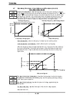
8.7
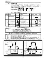
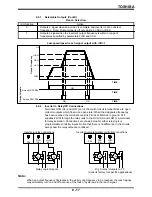
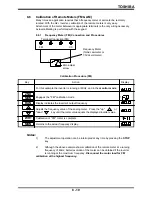
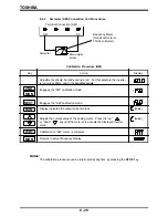
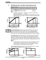
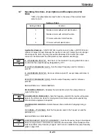
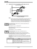
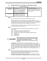
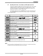
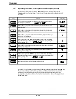
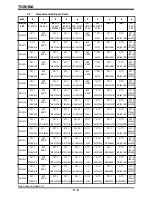
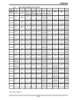
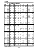
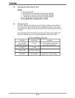
Operating Functions - Descriptions and Examples (Cont'd)
The three (3) parameters in
2nd
Function
9
on the G2+ allow the user to do a number
of different setups. The access to the inverter can be totally locked out, or select
functions can be locked out. By using these three parameters the inverter can be
programmed to function in a number of different ways.
The following example shows how to
Start-Stop
the unit via the touch-pad only and
have the
frequency
set by an external source only by changes to the paramenters
located in
2nd
function
9.
8 - 29
The inverter must always be placed in the function mode before
accessing any function.
When this key is pressed the inverter is placed into the second
function files.
When this key is pressed the inverter is placed into the second
function file number 9.
When this key is pressed the standard factory adjustment range
setting of 7 is displayed.
When the keys
2
and
WRT
are pressed in order then the factory
adjustment range setting of 2 is written into memory replacing the
factory setting of 7.
When this key is pressed the second menu item under the 2nd 9
functions is displayed.
When this key is pressed the standard factory adjustment range
setting of 7 is displayed.
When the keys
1
and
WRT
are pressed in order then the factory
adjustment range setting of 1 is written into memory replacing the
factory setting of 7.
Returns the inverter to the original monitor mode.
Key
Action
Display
MON
2ND
READ
2
WRT
9
NEXT
READ
WRT
1
MON
Note:
This setup accepts an external signal (4-20 mA, 0-5 VDC, & etc. ) through the terminal strip
and allows the user to start and stop the unit via the touch-pad.
Summary of Contents for TOSVERT-130G2+
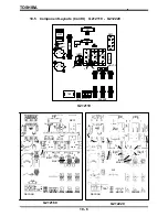
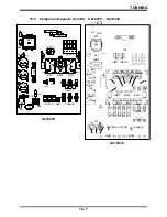
Page 112: ...TOSHIBA 10 6 Schematics 10 17 ...


