TOSHIBA
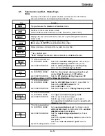
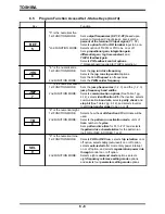
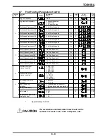
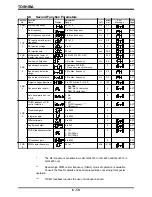
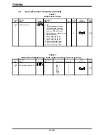
Lower limit frequency
0 to upper limit frequency
Hz
0
8-21
IV-ref. setting point #2
0 to 100
%
100
8-23
IV-ref. setting point #1
0 to 100
%
20
8-23
Acc/Dec #2 pattern
0: Linear
8-21
1: S-curve
0
2: C-curve
3
Upper limit frequency
0 to Max. frequency
Hz
80
8-21
4
Stall protection
10 to 150
%
150
8-22
Acc/Dec #1, #2 select
0: Acc/Dec #1
0
8-21
1: Acc/Dec #2
Voltage boost
0 to 30
%
3
8-21
Auto torque boost
0: Off
0
8-21
(voltage)
1: On
6.7
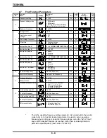
First Function Parameters
Function Function
Adjustment
Factory
Error
Ref.
No.
Name
Display
Range
Unit
Set
Message
Page
-
Frequency setting
0.1~400 *
Hz
0
8-6
Standard setting mode
1: 50Hz motor
3
8-21
2: 60Hz motor
0
3: Factory set (Reset to default)
(Always 0 display in this mode.)
Maximum frequency
30 to 400
Hz
80
8-21
6 - 8
1
Max. voltage frequency
25 to 400
Hz
60
8-21
V/f pattern
0: Constant torque
0
8-21
1: Variable torque
Acceleration time #1
0.1 to 6000
(SEE NOTE #1 PG. 6-9)
sec
10
8-21
Deceleration time #1
0.1 to 6000
sec
10
8-21
Acc/Dec #1 pattern
0: Linear
1: S-curve
0
8-21
2: C-curve
2
Acceleration time #2
0.1 to 6000
(SEE NOTE #1 PG. 6-9)
sec
10
8-21
Deceleration time #2
0.1 to 6000
sec
10
8-21
Overload detection
10 to 100
%
100
8-22
Overload detection curve
0: STD-motor, No soft stall
1: STD-motor, Soft stall
0
8-22
2: VF-motor, No soft stall
3: VF-motor, Soft stall
5
#1 output frequency
0 to Max. frequency
Hz
0
8-23
#2 output frequency
0 to Max. frequency
Hz
80
8-23
RR terminal priority
0: IV terminal input "on"
0
8-23
1: RR terminal input "on"
*
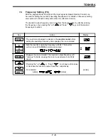
This is the operating frequency setting parameter. It is located within the monitor
mode but is not a true first function parameter. It is used to set an operating
frequency by scrolling up or down the frequency range, using the "up" or "down"
keys until the desired frequency is reached, rather than by entering data for a
particular output frequency (see section 7.2 and 8.3).
Summary of Contents for TOSVERT-130G2+
Page 112: ...TOSHIBA 10 6 Schematics 10 17 ...

