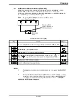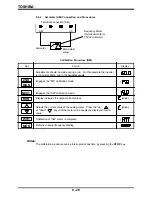
TOSHIBA
rCH function
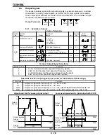
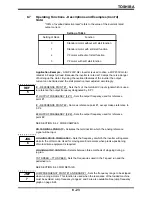
Action
0
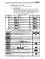
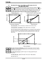
Outputs a signal when an acc/dec is complete and inverter is at a constant
frequency. Note: Output signal is off only during an ACC or DEC.
1
Outputs a signal when the inverter's output frequency is within a range of
frequencies specified by parameters FrCH and rrCH.
8.5.1
Selectable Outputs (Cont'd)
8 - 17
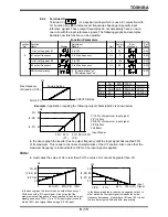
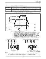
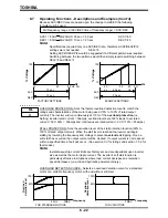
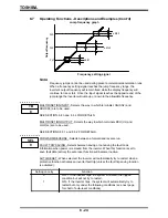
Reach Selection
ON
ON
ON
Across LOW-P24
Across RCH-P24
+rrCH
LOW
-rrCH
FrCH
Hz
TIME
Low speed/speed reach signal output with rCH=1
8.5.2
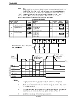
Inverter to Relay/PC Connections
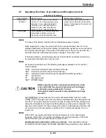
Terminals RCH (UL) and LOW (LL) of the control circuit terminal block are open
collector outputs which float in an open state. When the designated frequency
has been reached the terminals can sink 24Vdc at 50mAdc to ground. P24
supplies 24Vdc through the relay coils to the RCH (UL) and LOW (LL) terminals
for relay activation. Connections are shown below for either relay logic or
programmable controller inputs. Notice that there is no difference in the circuits
except how the relay outputs are utilized.
P24
LOW
(LL)
RCH
(UL)
Ry
Ry
P24
LOW
(LL)
RCH
(UL)
Ry
Ry
Note:
When an output frequency fluctuates in the vicinity of a frequency to be reached, the reach signal
may alternately turn on and off because of the lack of hysteresis in the reach signal.
Inverter-to-relay connections
Inverter-to-programmable controller connections
Dry Contact Outputs to PC
(Consult factory for specific applications)
Relay Logic Outputs
Output frequency
Output signals
TIME
TIME
Summary of Contents for TOSVERT-130G2+
Page 112: ...TOSHIBA 10 6 Schematics 10 17 ...

