background image

MAINTENANCE MANUAL


131 

STE 85357 


!


CAUTION


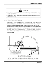
•  Be sure to use the grease designated by Toshiba Machine. 

Increase in internal pressure will adversely affect the starting torque and damage the 
internal seal.    To avoid this, be sure to observe the grease filling volume. 


5) 

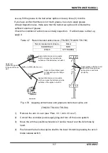
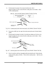
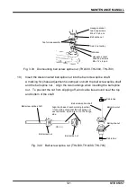
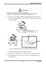
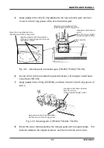
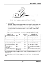
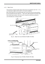
Secure Arm 1 to the base with sixteen (16) hexagon socket head cap screws 

(M4 x 20).    Apply grease to the O-ring (CO0545), and then mount it to the base 

groove side surface.   


Fig. 3.49    Mounting arm 1 and O-ring (THL500, THL600, THL700) 


6) 

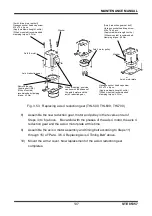
Connect the connectors (J1AS and J1BS) of the cables. 


7) 

Mount the axis 1 motor assembly.    (See 

“Para. 3.4.4, Mounting Axis 1 Motor.”) 


8) 

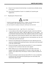
After changing Axis 1 motor, move Arm 1 by hand and check that there is no 

abnormal sound . 

Hexagon socket head cap screw   
M4 x 20 x 16 pcs.


(Apply medium strength Loctite.)


Base groove side surface


O-ring 
CO0545 

Summary of Contents for THL Series

Page 1: ...the final user of this product 2 Before using this product read through and completely understand this manual 3 After reading through this manual keep it nearby for future reference July 2012 TOSHIBA MACHINE CO LTD NUMAZU JAPAN Robot controller TSL3000 Robot controller TSL3000E Robot controller TS3000 Robot controller TS3000E ...

Page 2: ...THL700 THL800 THL900 and THL1000 Copyright 2012 by Toshiba Machine Co Ltd All rights reserved No part of this document may be reproduced in any form without obtaining prior written permission from Toshiba Machine Co Ltd The information contained in this manual is subject to change without prior notice to effect improvements ...

Page 3: ...fined in the product specifications manual catalog instruction manual etc In no event does the Guarantee cover any secondary or associated damage caused by malfunction of the product 2 Toshiba Machine repairs the product free of charge only when it malfunctioned after handling or use according to the instruction manual attached to the product within the specified warranty period 3 Exemption from r...

Page 4: ...ill not guarantee the basic performance of the product 2 If the customer did not observe the warnings and cautions described in this manual Toshiba Machine will not assume the responsibility for any consequential accident resulting in injury or death damage or trouble 3 Please note that the warnings cautions and other descriptions stipulated in this manual are only those which can be assumed by To...

Page 5: ... persons nearby to prevent damage to assets and to assure correct use Make sure that the following details indications and symbols are well understood before reading this manual Always observe the information that is noted Explanation of indications Indication Meaning of indication DANGER This means that incorrect handling will imminently lead to fatalities or serious injuries WARNING This means t...

Page 6: ... following items to use this product safely DANGER Prohibited DO NOT incinerate disassemble or charge the batteries Otherwise they may rupture Mandatory Be sure to remove the power plug of the controller from the power source before starting inspection or maintenance Batteries should be disposed of according to the user s in house regulations CAUTION Disassembly prohibited The user must NEVER repl...

Page 7: ...00 20 2 1 Details of Inspection 20 2 1 1 Check of Each Bolt or Screw for Clamping 20 2 1 2 Check of Each Cable and Air Tube for Abrasion 22 2 1 3 Check of Cable Clamp Tightening 23 2 1 4 Check of Each Axis for Operation 24 2 2 Layout of Robot Components and Drive Mechanism 25 2 3 Dismounting and Mounting Each Cover 26 2 3 1 Arm 2 Cover 27 2 3 2 Base Covers 28 2 4 Replacing Motor 31 2 4 1 Type of M...

Page 8: ...Reduction Gear 72 2 7 4 Mounting Axis 1 Reduction Gear 74 2 7 5 Dismounting Axis 2 Reduction Gear 77 2 7 6 Mounting Axis 2 Reduction Gear 78 2 7 7 Replacing Axis 4 Reduction Gear 80 3 Maintenance of the Main Robot THL500 THL600 THL700 82 3 1 Details of Inspection 82 3 1 1 Check of Each Bolt or Screw for Clamping 82 3 1 2 Check of Each Cable and Air Tube for Abrasion 84 3 1 3 Check of Cable Clamp T...

Page 9: ...it 122 3 7 Reduction Gear Replacement 126 3 7 1 Type of Reduction Gear 126 3 7 2 Reduction Gear Locations 127 3 7 3 Dismounting Axis 1 Reduction Gear 127 3 7 4 Mounting Axis 1 Reduction Gear 129 3 7 5 Dismounting Axis 2 Reduction Gear 133 3 7 6 Mounting Axis 2 Reduction Gear 134 3 7 7 Replacing Axis 4 Reduction Gear 136 4 Maintenance of the Main Robot THL800 THL900 THL1000 138 4 1 Details of Inspe...

Page 10: ... Unit and Applying Anticorrosive 175 4 6 4 Dismounting Ball Screw Spline Unit 178 4 6 5 Mounting Ball Screw Spline Unit 182 4 7 Reduction Gear Replacement 186 4 7 1 Type of Reduction Gear 186 4 7 2 Reduction Gear Locations 187 4 7 3 Dismounting Axis 1 Reduction Gear 187 4 7 4 Mounting Axis 1 Reduction Gear 188 4 7 5 Dismounting Axis 2 Reduction Gear 191 4 7 6 Mounting Axis 2 Reduction Gear 192 4 7...

Page 11: ...f Fuse X8GN X8GI Printed Board 240 7 3 6 Replacement of Output ICs X8GN X8GI Printed Board 241 8 Robot Home Point and Position Detector Error 244 8 1 Setting Robot Home Point 244 8 2 Position Detector Error 244 8 3 Replacing Position Detector or Encoder Batteries 248 8 3 1 Battery Box Location 249 8 3 2 Replacing Batteries 249 8 3 3 Battery Error Code 251 8 4 About Home Position 253 8 4 1 Location...

Page 12: ...parts 271 9 2 List of Replacement Parts Main Robot THL300 THL400 272 9 3 List of Replacement Parts Main Robot THL500 THL600 THL700 273 9 4 List of Replacement Parts Main Robot THL800 THL900 THL1000 274 9 5 List of Replacement Parts Controller THL300 THL400 TSL3000 275 9 6 List of Replacement Parts Controller THL500 THL1000 TSL3000 276 9 7 List of Replacement Parts Controller THL300 THL400 TSL3000E...

Page 13: ...ay 1 200hours 16 hours x 25 days 3 months When the system is operated for 24 hours per day 1 200hours 24 hours x 25 days 2 months If the system is operated for 16 hours per day it should be inspected every three 3 months If the number of hours of system operation per day becomes longer the regular inspection on the system must be done at shorter intervals 3 month check Running hours h Daily inspec...

Page 14: ...1 Para 3 1 1 Para 4 1 1 Robot installation bolts Motor set bolts Make sure that the cable clamps are tightened Arm 2 upper base Para 2 1 3 Para 3 1 3 Para 4 1 3 Make sure that no cut or scratch is found Clean the contaminant if any Entire robot Arm 2 interior Make sure that anti corrosive is properly applied If not apply anti corrosive Ball spline nut section end face of Ball screw shaft Para 2 6 ...

Page 15: ... noise is caused Entire robot Check for teaching position Tip of robot Replace the batteries for position detection with new ones Battery box Para 8 3 1 2 3 Overhaul Table 1 3 Overhaul Robot Description Maintenance parts Every 5 years Refer to THL300 THL400 THL500 THL600 THL700 THL800 THL900 THL1000 Check for the consumable parts and replace as necessary Motors belts ball screws reduction gears Ha...

Page 16: ...oller power is turned off the motor brake actuates even if the axis 3 motor brake release switch is kept pressed If the axis 3 motor brake release switch is pressed while the robot is carrying a heavy workpiece Axis 3 may drop suddenly To avoid this the customer should take all necessary measures by themselves 1 4 Maintenance Tools We recommend using the following tools for maintaining the robot a...

Page 17: ...ssure the appropriate clamping torque The places which do not fall under the table below are detailed in the paragraph of the replacement procedures Table 1 4 Clamping Torque Hexagon socket head cap screw M3 M4 M5 M6 M8 M10 M12 Set screws M3 M4 M5 M6 M8 M10 M12 M16 M20 Clamping torque 1 5N m 1 8N m 2 0 N m 4 7 N m 9 0 N m 15 N m 37 N m 75 N m 128 N m For the screws arranged on a circle for mountin...

Page 18: ... Repair If a fault has occurred or if repair is necessary turn off the controller power and contact the Toshiba Machine Service Department At this time advise us of the details of the fault and the following information stated on the robot and controller For the contact information of the Toshiba Machine Service Department please refer to Service Network Robot model Manufacture number Manufacture ...

Page 19: ...oller MUST NOT be modified or disassembled without a prior consent from Toshiba Machine CAUTION The user must NEVER replace or modify parts other than those described in the instruction manual Otherwise the performance may deteriorate or faults or accidents will be caused ...

Page 20: ...4 x 4 pcs of the tool set flange option which are clamped to the tool shaft are tightened completely If loose tighten them completely Using the hexagonal wrench key make sure that the mounting bolts M4 x 4 pcs which secure the tool to the tool flange are tightened completely If loose tighten them completely Loctite not necessary Fig 2 1 Tool set bolts Tool flange option Tool flange clamp bolt M4 x...

Page 21: ...bolt THL300 THL400 Location of bolt Type Bolts used Reference Para Axis 1 drive motor set bolt M4 x 12 4 pcs 2 4 4 Mounting Axis 1 Motor Axis 2 drive motor set bolt M4 x 12 4 pcs 2 4 6 Mounting Axis 2 Motor Axis 3 drive motor set bolt M3 x 10 4 pcs 2 4 8 Mounting Axis 3 Motor Axis 3 motor plate set bolt Flange head bolt M4 x 8 4 pcs 2 4 8 Mounting Axis 3 Motor Axis 4 drive motor set bolt M4 x 12 4...

Page 22: ...t the wear and disorder of the air tube as well as the pipe connection Make sure that the air tube is not worn out and is installed properly and pipe connection is correct Otherwise correct them Fig 2 3 Cable inspection locations THL300 THL400 Cable tie Check the cables around the axes 3 and 4 motor Make sure that the air tube is connected securely Check for wear around the cable outlets Make sure...

Page 23: ...force and tighten them When checking the tightened clamps check the one on the base side first By checking the tightness of the clamp on the base side first the twist of the cable can be adjusted slightly on the arm 2 side Make sure to tighten the clamps in the posture as shown in the figure below If the clamps are tightened while the arm is bent the cable cannot be installed correctly Fig 2 4 Cab...

Page 24: ...ach axis by hand and make sure that it can move smoothly For Axis 3 when the brake release switch is pressed the brake is released Take careful precautions at this time as the tool shaft may drop according to the weight of the hand and tool CAUTION If Axes 1 and 2 are moved to the vicinity of the operation range limit and then your hands are released Axes 1 and 2 may move by the counterforce of th...

Page 25: ...s is shown in Fig 2 5 Fig 2 5 Layout of robot mechanical components THL300 THL400 Axis 4 drive motor Axis 3 drive motor Ball screw spline shaft Axis 4 reduction gear Axis 1 reduction gear Axis 2 drive motor Axis 3 timing belt Ball spline nut Ball screw nut Axis 2 reduction gear Axis 4 timing belt Battery box Axis 1 drive motor ...

Page 26: ...taminant into the robot If the power is turned on while moisture or contaminant is left you may get an electric shock or the robot may malfunction which is very dangerous CAUTION When mounting the arm 2 cover and base cover take careful precautions not to catch any cable in it If the cable is bent and pushed by force it will be broken Each cable is secured to the plate etc with cable ties After th...

Page 27: ...head cap screws M3 x 16 and to cross truss head screws M3 x 10 x 2 pcs M3 x 6 x 8 pcs It is not necessary to apply Loctite when installing Fig 2 6 Arm 2 cover THL300 THL400 Socket head bolt M3 x 16 x 4 pcs Recommended clamping torque 1 47 N m Arm 2 cover Cross truss head screw M3 x 10 x 2 pcs Cross truss head screw M3 x 6 x 8 pcs ...

Page 28: ...ply Loctite to all the covers when installing Each of the base front cover and the base rear cover is secured to the base with six 6 cross truss head screws M4 x 8 They can be dismounted from the base when these fastening screws are removed but do not pull them with force as they are connected with the connectors inside Each of the left and right base side covers is secured to the base with four 4...

Page 29: ...85357 Fig 2 8 Base rear cover THL300 THL400 Fig 2 9 Base side covers THL300 THL400 Base rear cover Cross truss head screw M4 x 8 x 6 pcs Base side covers Hex countersunk screw M4 x 12x 4 pcs Hex countersunk screw M4 x 12 x 4 pcs ...

Page 30: ...MAINTENANCE MANUAL 30 STE 85357 Fig 2 10 Base bottom cover THL300 THL400 Base bottom cover Hex countersunk screw M4 x 8 x 4 pcs ...

Page 31: ...nnot be used due to positional shift etc Once the motor has been changed the mechanical home point origin or origin will shift and precise control will not be possible To avoid this home return operation is necessary after motor replacement For the home return procedures see Section 5 Robot Home Point and Position Detector Error 2 4 1 Type of Motor The motors employed in this robot are shown below...

Page 32: ...MAINTENANCE MANUAL 32 STE 85357 2 4 2 Motor Locations Fig 2 11 Motor locations THL300 THL400 Axis 3 motor Axis 4 motor Axis 1 motor Axis 2 motor ...

Page 33: ...ease may drip from the motor mounted section when pulling out the motor assembly At this time remove the O ring CO0534A being mounted on the base groove side surface Also when pulling out the motor assembly do not pull it with force as the motor connector is connected 3 Remove the connectors of the axis 1 motor i e J1AS and J1AP power drive cable and J1BS and J1BP encoder cables Fig 2 12 Dismounti...

Page 34: ...s shown in the figure below While pushing down each part to make tight contact and paying attention to the D cuts and the phases of the set screws tighten the set screws to fasten the wave generator Then pull out the fastening jigs In case the fastening jigs come out too easily remount them in such a way that some force is required to pull them out Fig 2 14 Mounting axis 1 wave generator THL300 TH...

Page 35: ... THL300 THL400 3 Apply an appropriate amount of grease onto the all surfaces of the wave generator mounted to the axis 1 motor Fig 2 16 Apply grease onto wave generator THL300 THL400 4 Connect the connectors of the axis 1 motor i e J1AS and J1AP power drive cable and J1BS and J1BP encoder cables O ring CO0534A Base groove side surface Cross sectional view Apply grease hatched areas Wave generator ...

Page 36: ...ers Fig 2 17 Mounting axis 1 motor assembly THL300 THL400 7 After changing Axis 1 motor move Arm 1 by hand and check that there is no abnormal sound before turning on the power 8 Mount the base front cover and the base side covers See Para 2 3 2 Base Covers 9 Turn on the power and set up the axis 1 home position to complete axis 1 motor replacement Check the coordinates of Axes 2 to 4 and set up t...

Page 37: ...s J2BS and J2BP axis 2 encoder cables It is recommended to take photos of the cable installation positions and the locations where cable ties are used so that these locations can be restored when needed 3 Remove the harness guide being secured with one 1 cross countersunk screw M3 x 6 and the support plate being secured with two 2 hexagon socket head cap screws M3 x 6 Fig 2 18 Dismounting harness ...

Page 38: ... axis 2 motor assembly Also remove the O ring CO0538A Fig 2 19 Dismounting axis 2 motor assembly THL300 THL400 5 Remove the wave generator from the axis 2 motor assembly Same as Step 4 in Para 2 5 3 Dismounting Axis 1 Motor Axis 1 drive motor set bolt Hexagon socket head cap screw M4 x 12 x 4 pcs Washer Axis 2 motor assembly O ring CO0538A ...

Page 39: ...the axis 2 motor Same as Step 3 in Para 2 4 4 Mounting Axis 1 Motor 4 Insert the axis 2 motor assembly into Arm 2 while paying attention to the motor s mounting phase the orientations of the decelerator main body and the wave generator when the motor is inserted align the long sides of the ovals of the reduction gear and wave generator and the position of the O ring it should not move Wave generat...

Page 40: ...upport plate with one 1 hex countersunk screw M3 x 8 application of Loctite not necessary and two 2 Cross countersunk screw M3 x 6 7 After changing the axis 2 motor move Arm 2 by hand and check that there is no abnormal sound Axis 2 drive motor set bolt Hexagon socket head cap screw M4 x 12 x 4 pcs Apply medium strength Loctite Axis 2 Motor Cross Section Diagram Install the O ring as shown in the ...

Page 41: ...HL400 9 Restore the cables in Arm 2 to the original conditions 10 Mount arm 2 cover 11 Turn on the power and set up the home positions of axes 2 to complete axis 2 motor replacement see Section 7 Robot Home Point and Position Detector Error Hexagon socket head cap screw M3 x 6 x 2 pcs Apply medium strength Loctite Cross countersunk screw M3 x 6 x 1 pc Harness guide Support plate ...

Page 42: ...ed so that these locations can be restored when needed 3 Disconnect connectors J3AS and J3AP power drive cables connectors J3BS and J3BP encoder cables and connectors J3DS and J3DP brake cables for Axis 3 which are connected to the connector panel 4 Loosen the axis 3 tension adjustment bolt M3 x 12 x 2 and hexagonal nuts and remove the flange head bolts M4 x 8 x 4 securing the axis 3 motor plate t...

Page 43: ...xis 3 motor plate with the hexagon socket head cap screws M3 x 10 x 4 pcs and the washers At this time be careful with the installation phases of the axis 3 motor and axis 3 motor plate 2 Mount the pulley for the axis 3 motor and fasten it with the set screws 4 x 5 x 2 pcs and 3 x 5 x 2 pcs Fasten the pulley while aligning the holes of the set screws of the pulley with the phases of the D cuts as ...

Page 44: ...Next tighten the tension adjustment bolts and fasten with the hexagon nuts Fig 2 25 Mounting axis 3 motor assembly THL300 THL400 Axis 2 drive motor set bolt Hexagon socket head cap screw M3 x 10 x 4 pcs Apply medium strength Loctite Set screws 4 x 5 x 2 pcs Set screws 3 x 5 x 2 pcs Axis Set screw holes Cross section B B B B D cuts Flat plane of motor axis Apply medium strength Loctite Axis 3 motor...

Page 45: ...9 Dismounting Axis 4 Motor 1 Remove the arm 2 cover See Para 2 3 1 Arm 2 Cover 2 Cut the cable ties of the cables with nippers It is recommended to take photos of the cable installation positions and the locations where cable ties are used so that these locations can be restored when needed 3 Disconnect connectors J4AS and J4AP power drive cables and connectors J4BS and J4BP encoder cables of the ...

Page 46: ...bolt cannot be aligned manually rotate the ball screw spline shaft and align the phases 6 Remove four 4 hexagon socket head cap screws M4 x 12 and washers that secure the axis 4 motor and then pull the axis 4 motor upward Fig 2 27 Dismounting axis 4 motor THL300 THL400 Axis 3 drive motor set bolt Hexagon socket head cap screws M4 x 12 x 4 pcs Washer Ball screw spline shaft Cap Remove in the arrow ...

Page 47: ... and J4AP power drive cables and J4BS and J4BP encoder cables 4 Restore the cables to the original conditions and then mount the arm 2 cover 5 Set up the home positions of Axes 3 and 4 to complete motor replacement During the replacement of the axis 4 motor it is necessary to set up the home position of Axis 3 6 Carry out a test operation of Axes 3 and 4 and make sure that each part operates prope...

Page 48: ...he lower limit Otherwise the shaft will drop due to the dead weight of the shaft or workpiece and your hand or finger may be caught Because the timing belt is disconnected the mechanical home point shifts and proper control cannot be done To avoid this home return operation is necessary after replacement of the timing belt For the home return procedures see Section 7 Robot Home Point and Position ...

Page 49: ... are used so that these locations can be restored when needed 3 Disconnect the axis 3 motor assembly For the disconnecting procedures see Steps 1 through 4 of Para 2 4 7 Dismounting Axis 3 Motor CAUTION The axis 3 motor is provided with a brake At replacement of the axis 3 timing belt this brake becomes inoperative Before starting the work therefore move down the shaft to the lower limit Otherwise...

Page 50: ... x 12 application of Loctite not necessary While pulling the axis 3 motor plate with the axis 3 tension adjustment bolts measure the tension with a tension meter Tighten the flange head bolt at the location where the tension reaches a value slightly smaller than 48 N because the tension gets larger by retightening of the flange head bolt Adjust so that the tensile value becomes between 48 and 64 N...

Page 51: ... 2 cover and perform home setting for Axes 3 and 4 This completes the replacement of the timing belt When replacing the 3rd axis timing belt be sure to set the 4th axis home position 8 Turn on the power While pressing the brake release switch in the servo off mode move the ball screw in the vertical direction Make sure of the smooth Tension meter Bolts for adjusting tension M3 x 12 x 2 pcs Hexagon...

Page 52: ...MAINTENANCE MANUAL 52 STE 85357 operation of the ball screw 9 Carry out a test operation of Axes 3 and 4 and make sure that each part operates properly ...

Page 53: ...rew spline shaft cannot function any further 1 Remove the arm 2 cover 2 Cut off the cable ties with nippers It is recommended to take photos of the routing of the cables and the locations where cable ties are used in advance in case they become necessary for restore 3 Remove the cross recessed flat head screw M3 x 6 x 1 pc and the hexagon socket head cap screws M3 x 6 x 2 pcs and then remove the h...

Page 54: ...s the ball screw spline shaft the ball screw nuts and the axis 3 bracket casting For more information about removal see item 5 in 2 5 7 Dismounting Axis 3 Motor 7 Remove the flange head bolts M4 x 8 x 4 pcs and then remove the axis 4 motor assembly and the axis 4 timing belt Fig 2 34 Dismounting axis 4 belt and motor assembly THL300 THL400 Axis 3 bracket sheet metal Hexagon socket head cap screw M...

Page 55: ...0 THL400 9 Fasten the ball screw nuts the ball screw spline shaft and the stoppers which were removed in step 6 above to Arm 2 For more information about mounting of the ball screw spline unit and the stoppers see 2 6 5 Mounting Ball Screw Spline Unit 10 Temporarily fasten the axis 4 motor assembly to Arm 2 with the flange head bolts M4 x 8 x 4 pcs Hexagon socket head cap screw M4 x 16 x 4 pcs App...

Page 56: ... that the tensile value becomes between 66 and 88 N when the flange head bolt is retightened Next tighten the tension adjustment bolts and fasten with the hexagon nuts If the bolt is not tightened any further the bolt can come out while the robot is in operation The values to be used for the tension meter are as shown in the table below Fig 2 37 Adjusting axis 4 tension THL300 THL400 Axis 4 timing...

Page 57: ... see Para 2 5 3 Replacing Axis 3 Timing Belt above 13 Arrange the connectors and cables as originally set See the pictures you took beforehand 14 Perform home setting for Axes 3 and 4 When replacing the 3rd axis timing belt be sure to set the 4th axis home position 15 Carry out a test operation of Axes 3 and 4 and make sure that the belt tension is appropriate 16 Attach the arm 2 cover Now replace...

Page 58: ...ming belt i e when mounting a new timing belt is the same as the value of tension at adjustment If the tension is appropriate mount the arm 2 cover Now the inspection is complete 3 When adjustment of the tension is required loosen the four 4 flange head bolts M4 x 8 securing the axis 3 and axis 4 motor plates respectively Measure the tension on the tension meter while adjusting the tension adjustm...

Page 59: ...ry dangerous CAUTION Because the timing belt nut and pulley are disconnected the mechanical home point shifts and proper control cannot be done To avoid this home return operation is necessary after replacement of the ball screw spline unit For the home return procedures see Section 7 Robot Home Point and Position Detector Error 2 6 1 Type of Ball Screw Spline Unit The ball screw spline unit used ...

Page 60: ...nt etc CAUTION When the grease has run short cut or scratch will be caused on the slide unit etc resulting in drop of the performance To avoid this take careful precautions to prevent shortage of the grease Be sure to use the grease designated by Toshiba Machine Apply anticorrosive when dried up If anticorrosive is not applied in such a case rust will be generated on the ball screw spline unit NEV...

Page 61: ...HL300 THL400 1 Remove the arm 2 cover see Para 2 3 1 Arm 2 Cover 2 Connect the controller power supply plug and turn off the servo system 3 Move the arm to a position where Axis 3 can be moved over the full stroke by hand 4 Push down the ball screw spline shaft to the lower limit while pressing the axis 3 brake release switch Apply rust preventive agent to the end face as well Apply grease uniform...

Page 62: ...8 Recommended grease THL300 THL400 Recommended grease Maker AFF grease THK Fig 2 40 Greasing lower side of ball screw spline unit THL300 THL400 6 Push up the shaft up to the upper limit while pressing the axis 3 brake release switch 7 Directly apply the grease by brash to the shaft area sticking up from the cover Apply the grease to such an extent that the shaft groove can be filled For the portio...

Page 63: ... unit THL300 THL400 8 Move the shaft up and down repeatedly while pressing the axis 3 brake release switch to fill the grease uniformly Wipe out the surplus grease Now the work completes Ball screw spline shaft Ball screw nut Apply the grease to this area Axis 3 brake release switch ...

Page 64: ...er replacement of the ball screw spline unit For the home return procedures see Section 7 Robot Home Point and Position Detector Error NEVER touch the ball screw spline unit with bare hand Otherwise the ball screw may be subjected to earlier rusting Be sure to gloves when you want to tough it In the descriptions on replacing the ball screw spline unit the procedures for changing the axis 3 and 4 m...

Page 65: ...topper which is secured to the ball screw nut Fig 2 42 Dismounting ball screw spline unit THL300 THL400 CAUTION When the ball screw nut integrated with the ball screw spline shaft is disconnected take utmost care not to cause the ball screw spline shaft to come off Otherwise the ball in the ball screw nut will drop and the ball screw nut integrated with the ball screw spline shaft cannot function ...

Page 66: ...e mounted accurately 9 Disconnect the axis 4 nut pulley secured to the ball spline nut with the hexagon socket head cap screw M4 x 10 x 6 pcs Fig 2 43 Dismounting ball screw spline nut THL300 THL400 10 Insert the disconnected ball spline nut into the ball screw spline shaft A marking for phase adjustment is stamped on both the ball screw spline shaft and the ball spline nut Align the two markings ...

Page 67: ...0 THL400 Cable ties Cable ties Ball screw spline shaft Ball screw nut Ball spline nut Ball screw spline shaft Ball screw nut Ball spline nut Align the phase of each marking number It should be noted that the ball spline nut has two marks which are not on the flange side ...

Page 68: ...ter replacement of the ball screw spline unit For the home return procedures see Section 5 Robot Home Point and Position Detector Error DO NOT pull out the ball screw shaft from the ball screw nut Otherwise the ball in the ball screw nut will drop and the ball screw nut integrated with the ball screw shaft cannot function any further NEVER touch the ball screw spline unit with bare hand Otherwise ...

Page 69: ...s 4 timing belt on the axis 4 pulley 6 Mount one stopper at 27 mm from the bottom end of the ball screw spline shaft Install the stoppers by aligning the notches of the stoppers with the leftmost spline groove 7 Move the ball screw spline shaft up and down to make it fit After that holding the 3rd axis bracket casting so that it does not move additionally tighten the hexagon socket head bolts M4 x...

Page 70: ... nut After home setting remove the mating mark from the old ball spline nut and attach it to the new one For the location of home point match mark see Para 7 4 4 Location of Robot Home Point Match Marks THL300 THL400 12 Carry out a test operation of Axes 3 and 4 and make sure that each part operates properly 13 Mount the arm 2 cover Now replacement of the ball screw spline unit completes Washer Pu...

Page 71: ...e reduction gear is disconnected the mechanical home point shifts and proper control cannot be done To avoid this home return operation is necessary after replacement of the reduction gear For the home return procedures see Section 5 Robot Home Point and Position Detector Error 2 7 1 Type of Reduction Gear The reduction gears used in this robot are shown below When you place an order for the reduc...

Page 72: ... Para 2 3 2 Base Covers 2 Remove four 4 hexagon socket head cap screws M4 x 12 and the washers that secure the axis 1 motor assembly pull out the axis 1 motor assembly and then remove the O ring CO0534A See Para 2 4 3 Dismounting Axis 1 Motor 3 Remove sixteen 16 hexagon socket head cap screws M3 x 20 that secure the base and then remove Arm 1 Axis 4 reduction gear Axis 2 reduction gear Axis 1 redu...

Page 73: ... the axis 1 reduction gear Also remove the O ring mounted in the groove of Arm 1 at this time Also remove the liquid gasket attached to the base mounting surface of the axis 1 reduction gear with the back of a cutter or a similar tool without damaging 5 Remove the wave generator from the axis 1 motor See Para 2 4 3 Dismounting Axis 1 Motor Fig 2 49 Dismounting axis 1 reduction gear THL300 THL400 H...

Page 74: ...ing the reduction gear take careful precautions not to break the O ring 1 Mount a new wave generator provided as an accessory with a new reduction gear For the mounting procedure see item 1 in Para 2 4 4 Mounting Axis 1 Motor 2 Cleanly wipe off dusts and stains on the axis 1 reduction gear of Arm 1 Apply grease to an O ring attached to the new reduction gear and then mount it in the O ring groove ...

Page 75: ...plication of grease to axis 1 reduction gear THL300 THL400 CAUTION Be sure to use the grease designated by Toshiba Machine Increase in internal pressure will adversely affect the starting torque and damage the internal seal To avoid this be sure to observe the grease filling volume Amount of grease filled in Axis 1 13 g Apply liquid gasket Cross sectional view Mark About the thickness of the mark ...

Page 76: ...Para 2 4 4 Mounting Axis 1 Motor 8 Manually move the 1st arm and make sure of its smooth movement 9 Mount the base front cover and the base side covers See Para 2 3 2 Base Covers 10 Set up the axis 1 home position to complete axis 1 reduction gear replacement 11 Carry out a test operation of Axis 1 to make sure that each part operates properly Hexagon socket head cap screw M3 x 20 x 16 pcs Apply m...

Page 77: ...gon socket head cap screws M3 x 16 that secure Arm 2 and the reduction gear 5 Remove eight 8 hexagon socket head cap screws M3 x 25 that secure the axis 2 reduction gear mounted to Arm 1 and then remove the axis 2 reduction gear At this time remove the O ring mounted in the O ring groove of Arm 1 At this time remove the liquid gasket attached to the base mounting surface of the axis 1 reduction ge...

Page 78: ...gear set surface When mounting the reduction gear take careful precautions not to break the O ring 1 Mount the wave generator attached to the new reduction gear to the axis 2 motor At this time apply grease to the O ring CO0538A and then mount it to the axis 2 motor flange rabbet See Para 2 4 6 Mounting Axis 2 Motor 2 Cleanly wipe off dusts and stains on the reduction gear of Arm 1 Apply grease to...

Page 79: ...s and then mount Arm 2 cover For the installation procedure see 2 4 5 Installation of the 2nd axis motor 8 Manually move the 2nd arm and make sure of its smooth movement Hexagon socket head cap screw M3 x 16 x 8 pcs Apply medium strength Loctite Apply liquid gasket Hexagon socket head cap screw M3 x 25 x 8 pcs Apply medium strength Loctite Axis 2 reduction gear Mount the O ring attached to the red...

Page 80: ...the time of re assembling 3 Referring to 2 5 4 Replacement of 4th axis timing belt remove only the 3rd axis motor assembly and 4th axis motor assembly from the 2nd arm Other parts need not be removed 4 Remove the cap attached to the lateral side of the axis 4 reduction gear then loosen the coupling bolt M3 securing the axis 4 motor shaft and the input shaft of the axis 4 reduction gear 5 Remove th...

Page 81: ...n Gear completes Axis 4 drive motor set bolt Hexagon socket head cap screw M4 x 12 x 4 pcs Apply medium strength Loctite When mounted recommended clamping torque 2 3 Nm Washer Axis 4 reduction gear set bolt Hexagon socket head cap screw M5 x 16 x 4 pcs Apply medium strength Loctite When mounted recommended clamping torque 6 2 Nm Axis 4 motor pulley Washer Axis 4 motor plate Hexagon socket head cap...

Page 82: ...y If loose tighten them completely Using the hexagonal wrench key make sure that the mounting bolts M4 x 4 pcs which secure the tool to the tool flange are tightened completely If loose tighten them completely Loctite not necessary Fig 3 1 Tool set bolts 2 Robot Installation Bolts Make sure using the hexagonal wrench key that the installation bolts of the main robot base are tightened completely I...

Page 83: ... x 16 4 pcs 3 4 4 Mounting Axis 1 Motor Axis 2 drive motor set bolt M4 x 14 4 pcs 3 4 6 Mounting Axis 2 Motor Axis 3 drive motor set bolt M4 x 12 4 pcs 3 4 8 Mounting Axis 3 Motor Axis 3 motor plate set bolt Flange head bolt M4 x 10 4 pcs 3 4 8 Mounting Axis 3 Motor Axis 4 drive motor set bolt M4 x 12 4 pcs 3 4 10 Mounting Axis 4 Motor Axis 4 reduction gear set bolt M5 x 16 4 pcs 3 7 7 Replacing A...

Page 84: ... as well as the pipe connection Make sure that the air tube is not worn out and is installed properly and pipe connection is correct Otherwise correct them Fig 3 3 Cable inspection locations THL500 THL600 THL700 Make holes on the metal plate cover and fasten the air tubes with bolts and nuts The customer is kindly requested to make preparations Make sure that the air tube is connected securely Che...

Page 85: ...ce and tighten them When checking the tightened clamps check the one on the base side first By checking the tightness of the clamp on the base side first the twist of the cable can be adjusted slightly on the arm 2 side Make sure to tighten the clamps in the posture as shown in the figure below If the clamps are tightened while the arm is bent the cable cannot be installed correctly Fig 3 4 Cable ...

Page 86: ...r source then keep the EMERGENCY pushbutton switch in the depressed condition Move each axis by hand and make sure that it can move smoothly For Axis 3 when the brake release switch is pressed the brake is released Take careful precautions at this time as the tool shaft may drop according to the weight of the hand and tool ...

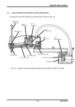
Page 87: ...s shown in Fig 3 5 Fig 3 5 Layout of robot mechanical components THL500 THL600 THL700 Axis 4 drive motor Axis 3 drive motor Ball screw spline shaft Ball screw nut Axis 1 reduction gear Axis 4 reduction gear Axis 1 drive motor Battery box Axis 2 reduction gear Axis 4 timing belt Axis 3 timing belt Ball spline nut Axis 2 drive motor ...

Page 88: ...inant into the robot If the power is turned on while moisture or contaminant is left you may get an electric shock or the robot may malfunction which is very dangerous CAUTION When mounting the arm 2 cover and base rear cover take careful precautions not to catch any cable in it If the cable is bent and pushed by force it will be broken Each cable is secured to the plate etc with cable ties After ...

Page 89: ...not interfere with the ball screw stopper 3 3 2 Base Covers There are four 4 types of base covers base front cover base rear cover base side cover and base cover It is not necessary to apply Loctite to all the covers when installing Each of the base front cover and the base rear cover is secured to the base with six 6 cross truss head screws M4 x 6 They can be dismounted from the base when these f...

Page 90: ...the base with six 6 hex countersunk screws M4 x 12 The base cover is secured to the base with six 6 hex countersunk screws M4 x 8 Fig 3 7 Base front cover THL500 THL600 THL700 Fig 3 8 Base rear cover THL500 THL600 THL700 Base rear cover Cross truss head screw M4 x 6 x 6 pcs Base front cover Cross truss head screw M4 x 6 x 6 pcs ...

Page 91: ...3 9 Base side covers THL500 THL600 THL700 Fig 3 10 Base bottom cover THL500 THL600 THL700 Base side covers Hex countersunk screw M4 x 12 x 6 pcs Hex countersunk screw M4 x 12 x 6 pcs Base bottom cover Hex countersunk screw M4 x 8 x 6 pcs ...

Page 92: ... they cannot be used due to positional shift etc Once the motor has been changed the mechanical home point origin or origin will shift and precise control will not be possible To avoid this home return operation is necessary after motor replacement For the home return procedures see Section 7 Robot Home Point and Position Detector Error 3 4 1 Type of Motor The motors employed in this robot are sho...

Page 93: ...ode AC servo motor Axis 1 S875289 Y610A3M20 Axis 2 S875290 Y610A3M30 Axis 3 S746337 Y610A3430 Axis 4 S875291 Y610A3M40 Key Axis 3 Square key 4 x 4 x 16 The key to be used with Axis 2 is attached to the motor 3 4 2 Motor Locations Fig 3 11 Motor locations THL500 THL600 THL700 Axis 1 motor Axis 2 motor Axis 3 motor Axis 4 motor ...

Page 94: ...ed on the base groove side surface Also when pulling out the motor assembly do not pull it with force as the motor connector is connected 3 Remove the connectors of the axis 1 motor i e J1AS and J1AP power drive cable and J1BS and J1BP encoder cables Fig 3 12 Dismounting axis 1 motor assembly THL500 THL600 THL700 4 Remove the hexagon socket head cap screw M4 x 10 x 1 pc from the end of the axis wh...

Page 95: ...with pliers or the like and then tighten the hexagon socket head cap screw M4 x 10 x 1 pc at the end of the axis Use a cushioning material such as a waste cloth to protect the wave generator from being scratched when securing it Fig 3 14 Mounting axis 1 wave generator THL500 THL600 THL700 Holding plate Wave generator Protrusion Hexagon socket head cap screws M4 x 10 x 1 pc Axis 1 motor Holding pla...

Page 96: ...rease onto wave generator THL500 THL600 THL700 4 Connect the connectors of the axis 1 motor i e J1AS and J1AP power drive cable and J1BS and J1BP encoder cables 5 Insert the axis 1 motor assembly into the base while paying attention to the motor s mounting phase the orientations of the reduction gear main body and the wave generator when the motor is inserted and the position of the O ring it shou...

Page 97: ...ra 3 3 2 Base Covers 9 Turn on the power and set up the axis 1 home position to complete axis 1 motor replacement Check the coordinates of Axes 2 to 4 and set up the home position if necessary See Section 7 Robot Home Point and Position Detector Error CAUTION Do not forget to mount the O ring If the O ring is not mounted grease will leak from the motor mounted surface Axis 1 drive motor set bolt H...

Page 98: ...ke photos of the cable installation positions and the locations where cable ties are used so that these locations can be restored when needed 3 Remove the harness guide being secured with one 1 hex countersunk screw M4 x 8 and the support plate being secured with two 2 hexagon socket head cap screws M4 x 8 Fig 3 18 Dismounting harness guide and support plate THL500 THL600 THL700 Hexagon socket hea...

Page 99: ...tor to the axis 2 motor Same as Step 1 in Para 3 4 4 Mounting Axis 1 Motor 3 Apply an appropriate amount of grease onto the all surfaces of the wave generator mounted to the axis 2 motor Same as Step 3 in Para 3 5 4 Mounting Axis 1 Motor 4 Insert the axis 2 motor assembly into Arm 2 while paying attention to the motor s mounting phase the orientations of the decelerator main body and the wave gene...

Page 100: ...M4 x 8 application of Loctite not necessary and two 2 hexagon socket head cap screws 4 x 8 7 Move Arm 2 by hand and check that there is no abnormal sound before turning on the power 8 Connect J2AS and J2AP axis 2 power drive cables J2BS and J2BP axis 2 encoder cables Axis 2 Motor Cross Section Diagram Install the O ring as shown in the figure Axis 2 drive motor set bolt Hexagon socket head cap scr...

Page 101: ...es in A 2 to the original conditions 10 mount Arm 2 cover 11 Turn on the power and set up the home positions of axes 2 to complete axis 2 motor replacement see Section 7 Robot Home Point and Position Detector Error Hexagon socket head cap screw M4 x 8 x 2 pcs Harness guide Support plate Hex countersunk screw M4 x 8 x 1 pc ...

Page 102: ...ions and the locations where cable ties are used so that these locations can be restored when needed 3 Disconnect connectors J3AS and J3AP power drive cables connectors J3BS and J3BP encoder cables and connectors J3DS and J3DP brake cables for the axis 3 which are connected to the connector panel 4 Loosen the axis 3 tension adjustment bolt M4 x 16 x 2 and hexagonal nuts and remove the flange head ...

Page 103: ... should exist between the motor shaft and pulley 2 Secure the axis 3 motor to the axis 3 motor plate with four 4 hexagon socket head cap screws M4 x 12 and washers Be careful with the mounting phases of the axis 3 motor and the axis 3 motor plate at this time 3 Mount the key and the axis 3 motor pulley and then secure them with the holding plate washers and one 1 hexagon socket head cap screw M3 x...

Page 104: ... tighten and secure the temporarily tightened flange head bolts with hex nuts Fig 3 25 Mounting axis 3 motor assembly THL500 THL600 THL700 Washer Holding plate Pulley Key Hexagon socket head cap screws M3 x 8 x 1 pc Apply medium strength Loctite Axis 3 drive motor set bolt Hexagon socket head cap screw M4 x 12 x 4 pcs Apply medium strength Loctite Axis 3 motor plate Fasten so that the motor lead w...

Page 105: ...cations can be restored when needed 3 Disconnect connectors J4AS and J4AP power drive cables and connectors J4BS and J4BP encoder cables of the axis 4 motor 4 Remove the cap attached to the lateral side of the axis 4 reduction gear and loosen the coupling bolt M4 securing the axis 4 motor shaft and input shaft of the axis 4 reduction gear If the hexagonal hole of the bolt is out of phase adjust th...

Page 106: ...J4AS and J4AP power drive cables and J4BS and J4BP encoder cables 4 Restore the cables to the original conditions and then mount the arm 2 cover 5 Set up the home positions of Axes 3 and 4 to complete motor replacement During the replacement of the axis 4 motor it is necessary to set up the home position of Axis 3 6 Carry out a test operation of Axes 3 and 4 and make sure that each part operates p...

Page 107: ... limit Otherwise the shaft will drop due to the dead weight of the shaft or workpiece and your hand or finger may be caught Because the timing belt is disconnected the mechanical home point shifts and proper control cannot be done To avoid this home return operation is necessary after replacement of the timing belt For the home return procedures see Section 7 Robot Home Point and Position Detector...

Page 108: ...ough 4 of Para 3 4 7 Dismounting Axis 3 Motor CAUTION The axis 3 motor is provided with a brake At replacement of the axis 3 timing belt this brake becomes inoperative Before starting the work therefore move down the shaft to the lower limit Otherwise the shaft will drop due to the dead weight of the shaft or workpiece and your hand or finger may be caught 4 Remove the four 4 hexagon socket head c...

Page 109: ...ts M4 x 10 application of Loctite not necessary Move the ball screw spline unit up and down to make it fit in Apply tension using two 2 axis 3 tension adjustment bolts M4 x 16 application of Loctite not necessary While pulling the axis 3 motor plate with the axis 3 tension adjustment bolts measure the tension with a tension meter Tighten the flange head bolt at the location where the tension reach...

Page 110: ...500 THL600 THL700 8 Connect the connectors and return them to their original location mount Arm 2 cover and perform home setting for Axes 3 and 4 This completes the replacement of the timing belt 9 Carry out a test operation of Axes 3 and 4 and make sure that each part operates properly Tension meter Bolts for adjusting axis 3 tension M4 x 16 x 2 pcs Hexagon nuts Flange head bolt M4 x 10 x 4 pcs A...

Page 111: ...e ball screw spline shaft For the disconnecting procedures see Steps 1 through 5 of Para 3 5 3 Replacing Axis 3 Timing Belt 2 Loosen two 2 tension adjustment bolts M4 x 16 for the axis 4 remove four 4 flange head bolts M4 x 10 securing the axis 4 motor plate and then pull out the axis 4 motor assembly Pull out the axis 4 timing belt upward and then install a new belt Fig 3 31 Dismounting harness g...

Page 112: ...tion where the tension reaches a value slightly smaller than 150 N because the tension gets larger by retightening of the flange head bolt Adjust so that the tensile value becomes between 150 and 180 N when the flange head bolt is retightened After that gradually tighten the tension adjusting bolt and fix it with a nut If the tension adjusting bolt is not tightened in this step the tension adjusti...

Page 113: ...ee Para 3 4 8 Mounting Axis 3 Motor and Para 3 5 3 Replacing Axis 3 Timing Belt above 7 Arrange the connectors and cables as originally set See the pictures you took beforehand 8 Perform home setting for Axes 3 and 4 9 Carry out a test operation of Axes 3 and 4 and make sure that the belt tension is appropriate 10 Attach the arm 2 cover Now replacement of the axis 4 timing belt completes Bolts for...

Page 114: ... the following table Note that the value of tension at replacement of timing belt i e when mounting a new timing belt is the same as the value of tension at adjustment If the tension is appropriate mount the arm 2 cover Now the inspection is complete 3 When adjustment of the tension is required loosen the four 4 flange head bolts M4 x 10 securing the axis 3 and axis 4 motor plates respectively Mea...

Page 115: ...e timing belt nut and pulley are disconnected the mechanical home point shifts and proper control cannot be done To avoid this home return operation is necessary after replacement of the ball screw spline unit For the home return procedures see Section 7 Robot Home Point and Position Detector Error 3 6 1 Type of Ball Screw Spline Unit The ball screw spline unit used in this robot is shown below Wh...

Page 116: ...ipment etc CAUTION When the grease has run short cut or scratch will be caused on the slide unit etc resulting in drop of the performance To avoid this take careful precautions to prevent shortage of the grease Be sure to use the grease designated by Toshiba Machine Apply anticorrosive when dried up If anticorrosive is not applied in such a case rust will be generated on the ball screw spline unit...

Page 117: ...HL500 THL600 THL700 1 Remove the arm 2 cover see Para 3 3 1 Arm 2 Cover 2 Connect the controller power supply plug and turn off the servo system 3 Move the arm to a position where Axis 3 can be moved over the full stroke by hand 4 Push down the ball screw spline shaft to the lower limit while pressing the axis 3 brake release switch upside without arm 2 cover downside Apply rust preventive agent t...

Page 118: ...s 3 brake release switch 7 Directly apply the grease by brash to the shaft area sticking up from the cover Apply the grease to such an extent that the shaft groove can be filled Wipe out the surplus grease Fig 3 37 Greasing upper side of ball screw spline unit THL500 THL600 THL700 8 Move the shaft up and down repeatedly while pressing the axis 3 brake release switch to fill the grease uniformly Wi...

Page 119: ... spline unit For the home return procedures see Section 7 Robot Home Point and Position Detector Error NEVER touch the ball screw spline unit with bare hand Otherwise the ball screw may be subjected to earlier rusting Be sure to gloves when you want to tough it In the descriptions on replacing the ball screw spline unit the procedures for changing the axis 3 and 4 motors and timing belts are not i...

Page 120: ...e ball screw nut will drop and the ball screw nut integrated with the ball screw spline shaft cannot function any further 8 Remove the hexagon socket head cap screw M4 x 12 x 6 pcs securing the ball spline nut and pull out the ball spline nut downward If the ball spline nut is hard to remove screw a bolt into the ball spline nut tap M4 to remove it 9 Disconnect the axis 4 nut pulley secured to the...

Page 121: ...nut from slipping off wind cable ties around near the top and bottom of the shaft Fig 3 40 Ball screw spline nut THL500 THL600 THL700 Hexagon socket head cap screws M4 x 12 x 6 pcs Washer Hexagon socket head cap screws M5 x 12 x 6 pcs Tap for disassembly Ball spline nut Axis 4 nut pulley Cable ties Cable ties Ball screw spline shaft Ball screw nut Ball spline nut Ball screw spline shaft Align the ...

Page 122: ...acement of the ball screw spline unit For the home return procedures see Section 7 Robot Home Point and Position Detector Error DO NOT pull out the ball screw shaft from the ball screw nut Otherwise the ball in the ball screw nut will drop and the ball screw nut integrated with the ball screw shaft cannot function any further NEVER touch the ball screw spline unit with bare hand Otherwise the ball...

Page 123: ... four 4 hexagon socket head cap screws M4 x 16 6 Secure the axis 3 nut pulley to the ball screw nut with four 4 hexagon socket head cap screws M5 x 20 and washers Hexagon socket head cap screw M5 x 12 x 6 pcs Apply medium strength Loctite Hexagon socket head cap screw M4 x 12 x 6 pcs Apply medium strength Loctite Washer Fasten so that the removal tap faces the direction of the arrow Ball spline nu...

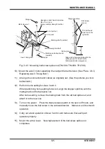
Page 124: ... Mount a stopper at a position 42 mm from both the top and the bottom of the ball screw spline shaft When mounting each stopper align its split line with the left end of the spline groove 9 Manually move the shaft in the vertical direction Make sure of its smooth operation After that hold the bracket so that it does not move and tighten the bolt temporarily locking the 3rd axis bracket Hexagon soc...

Page 125: ... power Press the brake release switch in the servo off mode and manually move the ball screw in the vertical direction Make sure of its smooth operation 14 Carry out a test operation of Axes 3 and 4 and make sure that each part operates properly 15 Mount the arm 2 cover Now replacement of the ball screw spline unit completes 42 Align each stopper split line with the spline groove on the left of th...

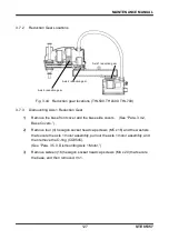
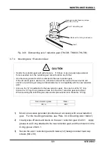
Page 126: ...tion gear is disconnected the mechanical home point shifts and proper control cannot be done To avoid this home return operation is necessary after replacement of the reduction gear For the home return procedures see Section 5 Robot Home Point and Position Detector Error 3 7 1 Type of Reduction Gear The reduction gears used in this robot are shown below When you place an order for the reduction ge...

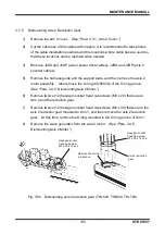
Page 127: ...s See Para 3 4 2 Base Covers 2 Remove four 4 hexagon socket head cap screws M5 x 16 and the washers that secure the axis 1 motor assembly pull out the axis 1 motor assembly and then remove the O ring CO0545 See Para 3 5 3 Dismounting Axis 1 Motor 3 Remove sixteen 16 hexagon socket head cap screws M4 x 20 that secure the base and then remove Arm 1 Axis 4 reduction gear Axis 2 reduction gear Axis 1 ...
Page 128: ...ead cap screws M4 x 30 that secure the axis 1 reduction gear to Arm 1 and then remove the axis 1 reduction gear Also remove the O ring mounted in the groove of Arm 1 at this time Also remove the liquid gasket attached to the base mounting surface of the axis 1 reduction gear with the back of a cutter or a similar tool without damaging 5 Remove the wave generator from the axis 1 motor See Para 3 4 ...

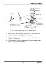
Page 129: ...ttached to the new reduction gear Be sure to set the O ring Unless the O ring is set grease will leak from the axis 1 reduction gear set surface When mounting the reduction gear take careful precautions not to break the O ring Recommended grease Maker SK 1A HDS 1 Mount a new wave generator provided as an accessory with a new reduction gear For the mounting procedure see Para 3 4 4 Mounting Axis 1 ...

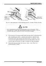
Page 130: ... the O ring into the O ring groove of the reducing gear Fig 3 48 Application of grease to axis 1 reduction gear THL500 THL600 THL700 Amount of grease filled in Axis 1 47 g Hexagon socket head cap screw M4 x 30 x 12 pcs Apply medium strength Loctite Axis 1 reduction gear Arm 1 Align the phases so that the protrusion of the axis 1 reduction gear and the relief hole of Arm 1 match Mount the O ring at...

Page 131: ...gon socket head cap screws M4 x 20 Apply grease to the O ring CO0545 and then mount it to the base groove side surface Fig 3 49 Mounting arm 1 and O ring THL500 THL600 THL700 6 Connect the connectors J1AS and J1BS of the cables 7 Mount the axis 1 motor assembly See Para 3 4 4 Mounting Axis 1 Motor 8 After changing Axis 1 motor move Arm 1 by hand and check that there is no abnormal sound Hexagon so...
Page 132: ... See Para 3 3 2 Base Covers 10 Set up the axis 1 home position to complete axis 1 reduction gear replacement Because the reduction gear is changed home position settings of Axes 2 through 4 are required 11 Carry out a test operation of Axis 1 to make sure that each part operates properly ...

Page 133: ... Also remove the O ring CO0583A of the O ring groove See Para 3 4 5 Dismounting Axis 2 Motor 6 Remove twelve 12 hexagon socket head cap screws M3 x 20 that secure Arm 2 and the reduction gear 7 Remove twelve 12 hexagon socket head cap screws M3 x 30 that secure the axis 2 reduction gear mounted to Arm 1 and then remove the axis 2 reduction gear At this time remove the O ring mounted in the O ring ...

Page 134: ...is set grease will leak from the axis 2 reduction gear set surface When mounting the reduction gear take careful precautions not to break the O ring 1 Mount the wave generator attached to the new reduction gear to the axis 2 motor See Para 3 4 6 Mounting Axis 2 Motor 2 Cleanly wipe off dusts and stains on the reduction gear of Arm 1 Apply grease to an O ring attached to the new reduction gear and ...

Page 135: ...L700 8 Mount the axis 2 motor assembly the harness guide and the support plate Put back the cables to the original locations and then mount the arm 2 cover Axis 2 reduction gear Arm 1 Mount the O ring attached to the reduction gear in the O ring groove Hexagon socket head cap screw M3 x 30 x 12 pcs Apply medium strength Loctite Align the phases so that the protrusion of the axis 2 reduction gear a...

Page 136: ...on positions and the locations where cable ties are used so that these locations can be restored when needed 3 Disconnect the axis 3 motor assembly and axis 4 motor assembly only from Arm 2 Other parts need not be removed 4 Remove the cap attached to the lateral side of the axis 4 reduction gear then loosen the coupling bolt M4 securing the axis 4 motor shaft and the input shaft of the axis 4 redu...

Page 137: ...r completes Remove the cap Coupling bolt M4 When mounted recommended clamping torque 4 3 Nm Washer When mounting exercise caution with the phases of the axis 4 motor and the axis 4 reduction gear Axis 4 motor Axis 4 reduction gear Washer Axis 4 motor plate Axis 4 motor pulley Hexagon socket head cap screw M4 x 12 x 6 pcs Apply medium strength Loctite When mounted recommended clamping torque 4 3 Nm...

Page 138: ... loose tighten them completely Using the hexagonal wrench key make sure that the mounting bolts M4 x 4 pcs which secure the tool to the tool flange are tightened completely If loose tighten them completely Loctite not necessary Fig 4 1 Tool mounting bolts 2 Robot Installation Bolts Make sure using the hexagonal wrench key that the installation bolts of the main robot base are tightened completely ...

Page 139: ... 4 4 4 Mounting Axis 1 Motor Axis 2 drive motor mounting bolt M4 x 12 4 pcs 4 4 6 Mounting Axis 2 Motor Axis 3 drive motor mounting bolt M4 x 12 4 pcs 4 4 8 Mounting Axis 3 Motor Axis 3 motor plate mounting bolt Flange head bolt M4 x 10 4 pcs 4 4 8 Mounting Axis 3 Motor Axis 4 drive motor mounting bolt M4 x 12 4 pcs 4 4 10 Mounting Axis 4 Motor Axis 4 reduction gear mounting bolt M5 x 16 4 pcs 4 7...

Page 140: ...nstallation Also inspect the wear and disorder of the air tube as well as the pipe connection Make sure that the air tube is not worn out and is installed properly and pipe connection is correct Otherwise correct them Fig 4 3 Cable inspection locations THL800 THL900 THL1000 Make holes on the metal plate cover and fasten the air tubes with bolts and nuts Make sure that the air tube is connected sec...

Page 141: ...ce and tighten them When checking the tightened clamps check the one on the base side first By checking the tightness of the clamp on the base side first the twist of the cable can be adjusted slightly on the arm 2 side Make sure to tighten the clamps in the posture as shown in the figure below If the clamps are tightened while the arm is bent the cable cannot be installed correctly Fig 4 4 Cable ...

Page 142: ...er source then keep the EMERGENCY pushbutton switch in the depressed condition Move each axis by hand and make sure that it can move smoothly For Axis 3 when the brake release switch is pressed the brake is released Take careful precautions at this time as the tool shaft may drop according to the weight of the hand and tool ...

Page 143: ...s shown in Fig 4 5 Fig 4 5 Layout of robot mechanical components THL800 THL900 THL1000 Axis 4 drive motor Axis 3 drive motor Ball screw spline shaft Ball screw nut Axis 4 reduction gear Axis 1 reduction gear Axis 2 drive motor Axis 1 drive motor Axis 2 reduction gear Battery box Axis 4 timing belt Axis 3 timing belt Ball spline nut ...

Page 144: ...minant into the robot If the power is turned on while moisture or contaminant is left you may get an electric shock or the robot may malfunction which is very dangerous CAUTION When mounting the arm 2 cover and base rear cover take careful precautions not to catch any cable in it If the cable is bent and pushed by force it will be broken Each cable is secured to the plate etc with cable ties After...

Page 145: ...THL800 THL900 THL1000 After the cover is mounted manually move up and down the ball screw spline shaft while pressing the brake release switch and make sure that the ball screw hole for the arm 2 cover will not interfere with the ball screw stopper Socket head bolt M3 x 6 x 4 pcs Recommended clamping torque 1 47 N m Socket head bolt M4 x 6 x 8 pcs Recommended clamping torque 1 47 N m Nylon washer ...

Page 146: ...e rear cover is secured to the base with six 6 cross truss head screws M4 x 8 They can be dismounted from the base when these fastening screws are removed but do not pull them with force as they are connected with the connectors inside Fig 4 7 Base front cover THL800 THL900 THL1000 Fig 4 8 Base rear cover THL800 THL900 THL1000 Base rear cover Cross truss head screw M4 x 8 x 6 pcs Base front cover ...

Page 147: ... they cannot be used due to positional shift etc Once the motor has been changed the mechanical home point origin or origin will shift and precise control will not be possible To avoid this home return operation is necessary after motor replacement For the home return procedures see Section 7 Robot Home Point and Position Detector Error 4 4 1 Type of Motor The motors employed in this robot are sho...

Page 148: ...otor Axis 1 S746328 Y610A34C0 Axis 2 S875290 Y610A3M30 Axis 3 S746337 Y610A3430 Axis 4 S875291 Y610A3M40 Key Axis 1 Square key 5 x 5 x 16 Axis 3 Square key 4 x 4 x 16 The key to be used with Axis 2 is attached to the motor 4 4 2 Motor Locations Fig 4 9 Motor locations THL800 THL900 THL1000 Axis 1 motor Axis 2 motor Axis 3 motor Axis 4 motor ...

Page 149: ...xis 1 motor base is connected by a pin MS5 15 Do not lose this pin The pin need not be removed 2 Remove the connector from the motor Lay the arms 1 and 2 down so that undue force will not be applied to the harness of the main body Fig 4 10 Removal of motor mount THL800 THL900 THL1000 3 Remove hexagon socket head bolts M5 x 30 x 16 pcs and washers securing the axis 1 motor assembly and pull out the...

Page 150: ... and remove the wave generator Fig 4 12 Dismounting axis 1 wave generator THL800 THL900 THL1000 5 Remove hexagon socket head bolts M4 x14 x 4 pcs and washers securing the axis 1 motor At the same time remove the O ring CO0540A from the axis 1 motor base as well Hexagon socket head bolts M5 x 30 x 16 pcs Washer O ring CO0551A Washer Wave generator Hexagon socket head bolt M4 x 12 x 1 pc ...

Page 151: ...t the O ring into the O ring groove of the axis 1 motor mount Use hexagon socket head bolts M4 x 14 x 4 pcs and washers to mount the axis 1 motor on the axis 1 motor mount In this case take care of the phases of the 1 axis motor mount and motor Fig 4 14 Mounting axis 1 motor THL800 THL900 THL1000 Washer Axis 1 motor mounting bolt Hexagon socket head bolts M4 x 14 x 4 pcs O ring CO0540A Fix it so t...

Page 152: ...is 1 motor Fig 4 16 Apply grease onto wave generator THL800 THL900 THL1000 5 Take care of the motor mounting phase and directions of the reduction gear and wave generator at the time of insertion of the motor elliptical portions of the reduction gear proper and wave generator should be adjusted Make sure that the O ring is not misaligned Then insert the axis 1 motor assembly into the reduction gea...

Page 153: ... Taking care of the pin MS5 15 fix the motor mount on the base using hexagon socket head bolts M6 x 16 x 8 pcs Fig 4 18 Mounting motor mount THL800 THL900 THL1000 8 Before turning on power subsequent to replacement of the axis 1 motor move the arm 1 by hand and make sure that there is no abnormal noise Washer Hexagon socket head bolts M5 x 30 x 16 pcs Hexagon socket head bolts M6 x 16 x 8 pcs Pin ...

Page 154: ...nted surface 4 4 5 Dismounting Axis 2 Motor 1 Disconnect the arm 2 cover See Para 4 3 1 Arm 2 Cover 2 Cut the cable ties of the cables with nippers or the like and remove J2AS and J2AP axis 2 power drive cables J2BS and J2BP axis 2 encoder cables It is recommended to take photos of the cable installation positions and the locations where cable ties are used so that these locations can be restored ...

Page 155: ...et head bolts M4 x 12 and washers securing the axis 2 motor Also remove the O ring CO0545A Fig 4 20 Dismounting axis 2 motor assembly THL800 THL900 THL1000 Hexagon socket head bolts M4 x 6 x 2 pcs Harness guide Hex countersunk screw M4 x 8 x 1 pc Support plate Hexagon socket head bolts M4 x 12 x 8 pcs O ring CO0545A Axis 2 motor assembly ...

Page 156: ...the O ring into the O ring groove of the axis 2 motor mount 2 Use hexagon socket head bolts M4 x 12 x 4 pcs and washers to mount the axis 2 motor on the axis 2 motor base In this case take care of the phases of the 2 axis motor and 2 axis motor base Axis 2 motor Washer Axis 1 motor mounting bolt Hexagon socket head bolts M4 x 12 x 4 pc Apply Locktite of intermediate strength Hexagon socket head bo...

Page 157: ...otor s mounting phase the orientations of the decelerator main body and the wave generator when the motor is inserted align the long sides of the ovals of the reduction gear and wave generator and the position of the O ring it should not move Apply grease SK 1A to the key and shaft end Hexagon socket head bolt M4 x 10 x 1 pc Apply Locktite of intermediate strength Washer Axis 2 motor assembly Fix ...

Page 158: ...0 7 Secure the harness guide and the support plate with one 1 hex countersunk screw M4 x 8 and two 2 hexagon socket head bolts M4 x 6 Fig 4 26 Mounting harness guide and support plate THL800 THL900 THL1000 Hexagon socket head bolts M4 x 12 x 8 pcs O ring CO0545A Axis 2 motor assembly Hexagon socket head bolts M4 x 6 x 2 pcs Harness guide Hex countersunk screw M4 x 8 x 1 pc Support plate ...

Page 159: ...nt of the axis 3 motor this brake becomes inoperative Before starting the work therefore move down the ball screw spline to the lower limit Otherwise the shaft will drop due to the dead weight of the shaft or workpiece and your hand or finger may be caught 1 Remove the arm 2 cover See Para 4 3 1 Arm 2 Cover 2 Cut the cable ties of the cables with nippers It is recommended to take photos of the cab...

Page 160: ...nd key 6 Remove four 4 hexagon socket head bolts M4 x 10 and washers that secure the axis 3 motor and then disassemble the axis 3 motor plate and the axis 3 motor Fig 4 28 Dismounting axis 3 motor pulley and plate THL800 THL900 THL1000 Washer Holding plate Pulley Key Hexagon socket head bolt M3 x 8 x 1 pc Axis 3 drive motor mounting bolt Hexagon socket head bolts M4 x 10 x 4 pcs Washer Axis 3 moto...

Page 161: ...n Fig 4 29 Mounting axis 3 pulley and plate THL800 THL900 THL1000 4 Hang the axis 3 motor timing belt to the arm 3 motor pulley and temporarily secure the axis 3 motor plate to Arm 2 with four 4 flange head bolts M4 x 10 application of Loctite not necessary Be careful with the motor mounting phase at this time Apply tension using two 2 axis 3 tension adjustment bolts M4 x 16 application of Loctite...

Page 162: ...bles with nippers It is recommended to take photos of the cable installation positions and the locations where cable ties are used so that these locations can be restored when needed 3 Disconnect connectors J4AS and J4AP power drive cables and connectors J4BS and J4BP encoder cables of the axis 4 motor 4 Remove the cap attached to the lateral side of the axis 4 reduction gear and loosen the coupli...

Page 163: ...the reduction gear with four 4 hexagon socket head bolts M4 x 12 and washers Be careful with the phase when mounting the motor Recommended clamping torque 2 3 N m 2 Tighten the coupling of the axis 4 reduction gear by means of the attached bolt M4 to mount the cap Recommended clamping torque 4 3 N m Axis 4 drive motor mounting bolt Hexagon socket head bolts M4 x 12 x 4 pcs Washer Ball screw spline...

Page 164: ... 3 and 4 to complete motor replacement During the replacement of the axis 4 motor it is necessary to set up the home position of Axis 3 6 Carry out a test operation of Axes 3 and 4 and make sure that each part operates properly Washer Axis 4 drive motor mounting bolt Hexagon socket head bolts M4 x 12 x 4 pcs Recommended clamping torque 2 3 N m Apply medium strength Loctite Fasten so that the motor...

Page 165: ...limit Otherwise the shaft will drop due to the dead weight of the shaft or workpiece and your hand or finger may be caught Because the timing belt is disconnected the mechanical home point shifts and proper control cannot be done To avoid this home return operation is necessary after replacement of the timing belt For the home return procedures see Section 7 Robot Home Point and Position Detector ...

Page 166: ...ties are used so that these locations can be restored when needed 3 Disconnect the axis 3 motor assembly For the disconnecting procedures see Steps 1 through 4 of Para 4 4 7 Dismounting Axis 3 Motor CAUTION The axis 3 motor is provided with a brake At replacement of the axis 3 timing belt this brake becomes inoperative Before starting the work therefore move down the shaft to the lower limit Other...

Page 167: ... THL800 THL900 THL1000 6 Hold the ball screw nut and the axis 3 bracket upward and mount a new timing belt 7 Temporarily clamp the axis 3 bracket on the arm 2 using four 4 hexagon socket head bolts M4 x 16 8 Fix the ball screw nut on the axis 3 bracket using six 6 hexagon socket head bolts M4 x 12 9 Move the ball screw in the vertical direction by ten reciprocating motions and align the center Aft...

Page 168: ...adjustment bolts measure the tension with a tension meter Tighten the flange head bolt at the location where the tension reaches a value slightly smaller than 49 N because the tension gets larger by retightening of the flange head bolt Adjust so that the tensile value becomes between 49 and 57 N when the flange head bolt is retightened Then secure with the hex nut The values to be used for the ten...

Page 169: ... axis 4 timing belt is replaced with a new one the axis 3 should be disassembled also due to the structure Therefore strictly observe the cautions on replacement of the axis 3 timing belt and motor also When the ball screw nut integrated with the ball screw spline shaft is disconnected take utmost care not to cause the ball screw spline shaft to come off Otherwise the ball in the ball screw nut wi...

Page 170: ...tion Then after routing the axes 3 and 4 timing belts mount the ball screw spline shaft For the mounting of the ball screw spline shaft see 4 6 5 Mounting of ball screw spline shaft Fig 4 37 Mounting ball screw shaft THL800 THL900 THL1000 Axis 4 motor assembly Bolts for adjusting axis 4 tension M4 x 16 x 2 pcs Hexagon nuts Axis 4 timing belt Axis 4 motor plate mounting bolt Flange head bolt M4 x 1...

Page 171: ...measure the tension with a tension meter Tighten the flange head bolt at the location where the tension reaches a value slightly smaller than 150 N because the tension gets larger by retightening of the flange head bolt Adjust so that the tensile value becomes between 150 and 180 N when the flange head bolt is retightened After that slightly tighten the tension adjusting bolt and fix it in positio...

Page 172: ... 4 5 3 Replacing Axis 3 Timing Belt above 8 Arrange the connectors and cables as originally set See the pictures you took beforehand 9 Perform home setting for Axes 3 and 4 10 Press the brake release switch and move Axis 3 in the vertical direction to make sure that there is no problem 11 Carry out a test operation of Axes 3 and 4 and make sure that the belt tension is appropriate 12 Attach the ar...

Page 173: ...alue of tension at replacement of timing belt i e when mounting a new timing belt is the same as the value of tension at adjustment If the tension is appropriate mount the arm 2 cover Now the inspection is complete 3 When adjustment of the tension is required loosen the four 4 flange head bolts M4 x 10 securing the axis 3 and axis 4 motor plates respectively Measure the tension on the tension mete...

Page 174: ...erous CAUTION Because the timing belt nut and pulley are disconnected the mechanical home point shifts and proper control cannot be done To avoid this home return operation is necessary after replacement of the ball screw spline unit For the home return procedures see Section 7 Robot Home Point and Position Detector Error 4 6 1 Type of Ball Screw Spline Unit The ball screw spline unit used in this...

Page 175: ...ral equipment etc CAUTION When the grease has run short cut or scratch will be caused on the slide unit etc resulting in drop of the performance To avoid this take careful precautions to prevent shortage of the grease Be sure to use the grease designated by Toshiba Machine Apply anticorrosive when dried up If anticorrosive is not applied in such a case rust will be generated on the ball screw spli...

Page 176: ...d grease to ball screw spline unit THL800 THL900 THL1000 1 Remove the arm 2 cover see Para 4 3 1 Arm 2 Cover 2 Connect the controller power supply plug and turn off the servo system 3 Move the arm to a position where Axis 3 can be moved over the full stroke by hand 4 Push down the ball screw spline shaft to the lower limit while pressing the axis 3 brake release switch Apply a rust inhibitor to th...

Page 177: ...d grease Maker AFF grease THK Fig 4 42 Greasing lower side of ball screw spline unit THL800 THL900 THL1000 6 Push up the shaft up to the upper limit while pressing the axis 3 brake release switch 7 Directly apply the grease by brash to the shaft area sticking up from the cover Apply the grease to such an extent that the shaft groove can be filled Wipe out the surplus grease Ball screw spline shaft...

Page 178: ...t cannot function any further Replacement of the ball screw spline unit involves mounting and dismounting of the axis 3 and 4 motors and timing belts Also observe the cautions on each work Because the motor timing belt nut and pulley are disconnected the mechanical home point shifts and proper control cannot be done To avoid this home return operation of axis 3 and 4is necessary after replacement ...

Page 179: ... followed by the upper and lower stoppers 3 Disconnect the axis 3 motor assembly Keep the axis 4 belt loose 4 Remove eight 8 hexagon socket head bolts M4 x 12 securing the ball screw nut and pull out the ball screw nut and ball screw spline shaft together as an integral structure During this work make sure that the ball screw nut and shaft will not be disconnected 5 Remove four 4 hexagon socket he...

Page 180: ...x 6 hexagon socket head bolts M4 x 12 securing the ball spline nut and pull out the ball spline nut downward If the ball spline nut is hard to remove screw a bolt into the ball spline nut tap M4 to remove it 10 Disconnect the axis 4 nut pulley secured to the ball spline nut with six 6 hexagon socket head bolts M5 x 12 When it is hard to disconnect screw the bolt into the tap for disassembly M4 mac...

Page 181: ...ut from slipping off wind cable ties around near the top and bottom of the shaft Fig 4 46 Ball screw spline nut THL800 THL900 THL1000 Hexagon socket head bolts M4 x 12 x 6 pcs Washer Hexagon socket head bolts M5 x 12 x 6 pcs Tap for disassembly Ball spline nut Axis 4 nut pulley Align the phase of each marking number It should be noted that the ball spline nut has two markings which are not located...

Page 182: ...er control cannot be done To avoid this home return operation is necessary after replacement of the ball screw spline unit For the home return procedures see Section 7 Robot Home Point and Position Detector Error DO NOT pull out the ball screw shaft from the ball screw nut Otherwise the ball in the ball screw nut will drop and the ball screw nut integrated with the ball screw shaft cannot function...

Page 183: ...d bolts M4 x 16 6 Secure the axis 3 nut pulley to the ball screw nut with four 4 hexagon socket head bolts M5 x 20 and washers Mount the upper stopper For the stopper mounting position see Fig 4 49 Ball spline nut Ball screw nut Ball screw spline shaft Hexagon socket head bolts M5 x 12 x 6 pcs Apply medium strength Loctite Washer Axis 4 nut pulley Hexagon socket head bolts M4 x 12 x 6 pcs Apply me...

Page 184: ...or draw out 8 Mount a stopper at a position 40 mm from the bottom of the ball screw spline shaft When mounting each stopper align its split line with the left end of the spline groove 9 Manually move the shaft several times in the vertical direction and make sure that the movement is smooth After that tighten the bolt temporarily clamping the axis 3 bracket In this case fix it by holding the axis ...

Page 185: ...e the mating mark from the old ball spline nut and attach it to the new one 13 Carry out a test operation of Axes 3 and 4 and make sure that each part operates properly 14 Mount the arm 2 cover Now replacement of the ball screw spline unit completes 40 Arm 2 Axis 3 timing belt Ball screw nut Stopper Marking on ball spline nut number Axis 3 bracket Spline groove Marking shaft number Do not pull out...

Page 186: ...ion gear is disconnected the mechanical home point shifts and proper control cannot be done To avoid this home return operation is necessary after replacement of the reduction gear For the home return procedures see Section 5 Robot Home Point and Position Detector Error 4 7 1 Type of Reduction Gear The reduction gears used in this robot are shown below When you place an order for the reduction gea...

Page 187: ...dismounted by two 2 or more persons When removing the Arm 1 mounting bolts take careful precautions because Arm 1 will drop Also if an excessively large impact is imposed on the arm the robot will be damaged 4 Remove twelve 12 hexagon socket head bolts M5 x 35 that secure the axis 1 reduction gear to Arm 1 and then remove the axis 1 reduction gear Also remove the O ring mounted in the groove of Ar...

Page 188: ...ositioning accuracy will deteriorate due to incompatibility with the new reduction gear Also use the O ring attached to the new reduction gear Be sure to set the O ring Unless the O ring is set grease will leak from the axis 1 reduction gear set surface When mounting the reduction gear take careful precautions not to break the O ring 1 Mount a new wave generator provided as an accessory with a new...

Page 189: ...he attached wave generator Also apply grease to the wave generator Additionally apply grease to an O ring attached to the new reduction gear and then mount it in the O ring groove of the reduction gear Hexagon socket head bolts M5 x 35 x 12 pcs Apply medium strength Loctite Arm 1 Align the phases so that the protrusion of the axis 1 reduction gear and the relief hole of Arm 1 match Mount the O rin...

Page 190: ...rve the grease filling volume 5 Mount the axis 1 motor assembly according to 4 4 4 Mounting of axis 1 motor and fix the Arm 1 on the base 6 Mount the base front cover See Para 4 3 2 Base Covers Amount of grease filled in Axis 1 60 g 断面図 Reduction gear proper Protrusion of axis 1 arm Mount the O ring attached to the reduction gear in the O ring groove The thickness of the wave generator Apply greas...

Page 191: ...en remove the axis 2 motor assembly Also remove the O ring CO0545A of the O ring groove See Para 4 4 5 Dismounting Axis 2 Motor 2 Remove sixteen 16 hexagon socket head bolts M4 x 20 that secure Arm 2 and the reduction gear 3 Remove twelve 12 hexagon socket head bolts M4 x 30 that secure the axis 2 reduction gear mounted to Arm 1 and then remove the axis 2 reduction gear At this time remove the O r...

Page 192: ...ring is set grease will leak from the axis 2 reduction gear set surface When mounting the reduction gear take careful precautions not to break the O ring 1 Mount the wave generator attached to the new reduction gear to the axis 2 motor See Para 4 4 6 Mounting Axis 2 Motor 2 Cleanly wipe off dusts and stains on the reduction gear of Arm 1 Apply grease to an O ring attached to the new reduction gear...

Page 193: ...545A and then mount it in the O ring groove of Arm 2 Fig 4 56 Mounting arm 2 THL800 THL900 THL1000 Hexagon socket head bolts M4 x 20 x 16 pcs Apply medium strength Loctite Apply grease to the O ring CO0545A and then mount it in the O ring groove Mount the O ring attached to the reduction gear in the O ring groove Align the phases so that the protrusion of the axis 2 reduction gear and the relief h...

Page 194: ...er See Para 4 3 1 Arm 2 Cover 2 Remove only the axes 3 and 4 motor assemblies from the arm 2 according to steps 1 and 2 of 4 5 4 Replacement of axis 4 timing belt 3 Remove the cap attached to the lateral side of the axis 4 reduction gear then loosen the coupling bolt M4 securing the axis 4 motor shaft and the input shaft of the axis 4 reduction gear 4 Remove four 4 hexagon socket head bolts M4 x 1...

Page 195: ...ement of axis 4 reduction gear Remove the cap Coupling bolt M4 When mounted recommended clamping torque 4 3 Nm Washer When mounting exercise caution with the phases of the axis 4 motor and the axis 4 reduction gear Axis 4 motor Axis 4 reduction gear Washer Axis 4 motor plate Axis 4 motor pulley Hexagon socket head bolts M4 x 12 x 6 pcs Apply medium strength Loctite When mounted recommended clampin...

Page 196: ... remove the power supply plug before starting the work CAUTION Before removing the controller cover for maintenance or inspection be sure to remove the power supply plug of the controller from the power source Also turn off the power breaker when connecting or disconnecting the power cable DO NOT touch the servo driver for at least two 2 minutes after the power supply has been removed The large ca...

Page 197: ...00 Table 5 1 Controller parts TSL3000 Part name Descriptions PS1 PS2 PS1 P5V PS2 P24V output switching power supply X8YC Main control printed board X8YX I O output printed board X8YS Servo power module X8YS unit servo power supply board PS1 P5V PS2 P24V X8YC main board X8YX I O board Controller weight 7kg ...

Page 198: ...nction To avoid this perform check on the air vent holes to make sure that air is flowing freely through them Fig 5 2 Controller side views TSL3000 1 If there is any obstacle move it away from the air vent hole so that air flow is not blocked 2 Make sure that no contaminant is left on the air vent holes If any contaminant is left on the vent hole remove it Air vent holes ...

Page 199: ...the key at front of controller for selecting the TEACH b Turn the EMERGENCY switch 1 clockwise and make sure that the EMERGENCY switch 1 turns off c Press the SERVO ON switch 2 on the teach pendant to turn on the servo power while keeping the ENABLE switch 3 at the neutral position and make sure that the SERVO ON LED 2 is illuminated Note The servo power cannot be turned on in the TESTRUN mode d P...

Page 200: ...gnals work properly a Connect the power supply plug to the power source to turn on the servo power Then turn on or trip the safety devices connected with external operation input signal emergency stop such as external emergency stop switch photoelectric type sensing safety device and foot switch to make sure that the servo power is turned off b Set ON the safety devices connected with external ope...

Page 201: ...ng the life the battery voltage will drop to below the voltage required for keeping the memory data resulting in the data being lost and faults caused by leakage of the battery liquid If the following alarm has occurred replace the battery with a new one 1 145 MAIN Battery alarm Fig 5 4 Location of lithium battery TSL3000 Table 5 2 Battery replacement TSL3000 Type of battery Manufacturer Battery s...

Page 202: ...from the main body 4 Remove the battery from the cable ties securing the battery For the battery position see Fig 5 4 5 Remove the battery connector from CN5 of the X8YC board Immediately connect the connector of the new battery to CN5 If the battery is kept removed for more than one 1 minute all memory data are lost Even if not used the lithium battery capacity decreases by natural discharge Use ...

Page 203: ...This unit uses an aluminum electrolytic capacitor and if the load current is large the running time is long and the ambient temperature is high the life will reduce As the life varies largely with the user s operating conditions 5 to 10 years replace the power supply unit every five 5 years for preventive maintenance Replacement procedures 1 Turn off the power breaker and disconnect the power supp...

Page 204: ... connected to the X8YC main board as well as the hand I O cable blue and the brake cable blue connected to the X8YX I O board 6 Remove the cables red x 1 line blue x 1 line black x 2 lines connected to the PS1 and the PS2 See Fig 4 10 When removing the interior panel unit be sure to remove the key Countersunk screws M3 x 6 x 8 pcs ACIN connector ...

Page 205: ... Controller interior TSL3000 Fig 5 7 Controller interior TSL3000 X8YC main board X8YX I O board Brake cable blue Hand I O cable blue SVIF cable blue DC cable blue and red Encoder cable blue X8YC main board rear side Controller front side view ...

Page 206: ...nit TSL3000 8 Remove four 4 sems screws M3 x 8 that secure each of the switching power supplies PS1 PS2 and then remove the switching power supplies from the interior panel unit Fig 5 9 Side view of interior panel unit assembly TSL3000 Pull out the interior panel unit Countersunk screw M3 x 6 x 1 pcs PS1 P5V LFA30 5 J1Y PS2 P24V LFA30 24 J1 DC cable biue DC cable red Sems screw M3 x 8 x 4 pcs Sems...

Page 207: ...moved interior panel unit into the controller and then secure it with one 1 countersunk screw M3 x 6 12 Connect the DC cable blue and red the SVIF cable blue and the encoder cable blue to the X8YC main board and also connect the hand I O cable blue and the brake cable blue to the X8YX I O board See Fig 4 7 13 Mount the cover to the main body using eight 8 countersunk screws M3 x 6 5 3 5 Replacemen...

Page 208: ...ler from the power source 2 Remove the fuse holder shown in the above figure To release the lock push and turn the holder 90 counterclockwise 3 Remove the fuse and set a new fuse in the fuse holder 4 Mount the fuse holder To lock the holder push and turn the holder 90 clockwise 5 Connect the power supply plug of the controller to the power source and make sure that no error will occur Rotate while...

Page 209: ...ntify an fault circuit remedy the cause then replace the ICs The relationship between the output ICs and output signals is shown below Fig 5 11 I O Board TSL3000 There are two types of transistor output ICs Refer to the following for the output types Output IC U5 System output signal DOUT13 DOUT17 Connector OUTPUT Output IC U4 System output signal DOUT9 DOUT12 Connector OUTPUT Output IC U3 User ou...

Page 210: ...G Toshiba 2 Type P M54562WP Mitsubishi Electric Replacement procedures 1 Turn off the breaker for power supply 2 Disconnect the ACIN connector from the controller 3 Remove eight 8 countersunk screws M3 x 6 that secure the cover and then remove the cover from the main body Fig 5 12 Removing cover TSL3000 Countersunk screw M3 x 6 x 8 pcs ...

Page 211: ...rom the outlet 7 Mount a new transistor output IC to the outlet Note Pay attention to the model number and orientation of the transistor output IC 8 Mount the X8YX board to the main body using five 5 sems screws M3 x 8 9 Connect the hand I O cable blue and the brake cable blue to the X8YX I O board and then mount the main body cover to the main body with eight 8 countersunk screws M3 x 6 10 Connec...

Page 212: ... remove the power supply plug before starting the work CAUTION Before removing the controller cover for maintenance or inspection be sure to remove the power supply plug of the controller from the power source Also turn off the power breaker when connecting or disconnecting the power cable DO NOT touch the servo driver for at least two 2 minutes after the power supply has been removed The large ca...

Page 213: ...ptions PS1 PS1 P5V P24V output switching power supply X8YV Main control printed board X8YJ I O output printed board X8YS Servo power module for 4 axes SRM1 SRM2 Safety relay modules X8YH unit servo power printed board X8YV Main control printed boar X8YJ I O printed board X8YZ Safety input board PS1 P5V P24V Safety relay modules SRM1 SRM2 Controller weight 13kg ...

Page 214: ...m check on the air vent holes to make sure that air is flowing freely through them Fig 6 2 Controller side views TSL3000E Fig 6 3 Controller rear views TSL3000E 1 If there is any obstacle move it away from the air vent hole so that air flow is not blocked 2 Make sure that no contaminant is left on the air vent holes If any contaminant is left on the vent hole remove it Air vent holes Air vent hole...

Page 215: ...the key at front of controller for selecting the TEACH b Turn the EMERGENCY switch 1 clockwise and make sure that the EMERGENCY switch 1 turns off c Press the SERVO ON switch 2 on the teach pendant to turn on the servo power while keeping the ENABLE switch 3 at the neutral position and make sure that the SERVO ON LED 2 is illuminated Note The servo power cannot be turned on in the TESTRUN mode d P...

Page 216: ...gnals work properly a Connect the power supply plug to the power source to turn on the servo power Then turn on or trip the safety devices connected with external operation input signal emergency stop such as external emergency stop switch photoelectric type sensing safety device and foot switch to make sure that the servo power is turned off b Set ON the safety devices connected with external ope...

Page 217: ...s used neglecting the life the battery voltage will drop to below the voltage required for keeping the memory data resulting in the data being lost and faults caused by leakage of the battery liquid If the following alarm has occurred replace the battery with a new one 1 145 MAIN Battery alarm Fig 6 5 Location of lithium battery TSL3000E Table 6 2 Battery replacement TSL3000E Type of battery Manuf...

Page 218: ...rom the main body 4 Remove the battery from the cable ties securing the battery For the battery position see Fig 6 5 5 Remove the battery connector from CN4 of the X8YV board Immediately connect the connector of the new battery to CN4 If the battery is kept removed for more than one 1 minute all memory data are lost Even if not used the lithium battery capacity decreases by natural discharge Use a...

Page 219: ... This unit uses an aluminum electrolytic capacitor and if the load current is large the running time is long and the ambient temperature is high the life will reduce As the life varies largely with the user s operating conditions 5 to 10 years replace the power supply unit every five 5 years for preventive maintenance Replacement procedures 1 Turn off the power breaker and disconnect the power sup...

Page 220: ...coder cable blue connected to the X8YV main board as well as the hand I O cable blue and the brake cable blue connected to the X8YJ I O board 6 Remove the cables blue x 1 line black x 1 lines connected to the PS1 See Fig 6 9 To remove the intermediate plate unit remove the key ten flat countersunk head screws M3 x 6 ACIN connector ...

Page 221: ...oller interior side view TSL3000E Fig 6 8 Controller interior front view TSL3000E X8YZ Safety input board X8YV main printed board Brake cable blue Hand I O cable blue SVIF cable blue DC cables blue and red X8YJ I O printed board Encoder cable blue ...

Page 222: ...cures the interior panel unit Pull out the interior panel unit toward the rear of the controller When removing the interior panel unit be sure to remove the key Fig 6 9 Removing interior panel unit TSL3000E three flat countersunk head screws M3 x 6 Remove the intermediate plate unit ...

Page 223: ...it assembly TSL3000E 9 Using four 4 sems screws M3 x 8 secure the new switching power supplies to the main body Note Never install the PS1 switching power supplies right and left in reverse 10 Attach a cable to the PS1 11 Insert the removed interior panel unit into the controller and then secure it with three 3 countersunk screw M3 x 6 PS1 P5V P24V LFB100F 0524 DC cable blue Four sems screws M3 x ...

Page 224: ... blue the SVIF cable blue and the encoder cable blue to the X8YV main board and also connect the hand I O cable blue and the brake cable blue to the X8YJ I O board See Fig 4 7 and 4 8 13 Mount the cover to the main body using ten 10 countersunk screws M3 x 6 ...

Page 225: ...the I O unit the fuse of the front of the TSL3000 controller is blown out If the alarm saying I O Fuse Broken 8 273 is displayed replace the fuse with a new one If the fuse of the output module has been blown out examine and identify a fault circuit remedy the cause then replace the fuse Fig 6 11 Changing fuse TSL3000E Turn it while pushing ...

Page 226: ...from the power source 2 Remove the fuse holder shown in the above figure To release the lock push and turn the holder 90 counterclockwise 3 Remove the fuse and set a new fuse in the fuse holder 4 Mount the fuse holder To lock the holder push and turn the holder 90 clockwise 5 Connect the power supply plug of the controller to the power source and make sure that no error will occur ...

Page 227: ... to remove the power supply plug before starting the work CAUTION Before removing the controller cover for maintenance or inspection be sure to remove the power supply plug of the controller from the power source Also turn off the power breaker when connecting or disconnecting the power cable DO NOT touch the servo driver for at least two 2 minutes after the power supply has been removed The large...

Page 228: ...MAINTENANCE MANUAL 228 STE 85357 7 2 Layout of Controller Parts Fig 7 1 Layout of controller parts TS3000 TS3000E X8G2 G3 X8GB X8GN X8GI X8GC X8GL R1 PS2 P5V PS1 P24V NF1 Controller weight 13kg ...

Page 229: ...Descriptions PS1 P24V output switching power supply PS2 P5V output switching power supply X8GC Main control printed board X8GN X8GI I O output printed board X8GL Servo logic printed board X8GI X8G3 Servo amplifier printed board X8GB Mother board R1 Regenerative resistor NF1 Noise filter ...

Page 230: ... view Right side view Fig 7 2 Controller side views TS3000 TS3000E a If there is any obstacle move it away from the air vent hole so that air flow is not blocked b Make sure that no contaminant is left on the air vent holes If any contaminant is left on the vent hole remove it c If the controller is placed sideways make sure that the air vent holes on the bottom surface of the controller are more ...

Page 231: ...tly Fig 7 3 Layout of control panel switches TS3000 TS3000E a Make sure that the EMERGENCY emergency stop switch 3 provided on the control panel functions properly 1 Set the key switch 4 to the INTERNAL mode 2 Press the SERVO ON switch 1 provided on the control panel to turn the servos on and make sure that the SERVO ON switch 1 LED is illuminated 3 Press the EMERGENCY switch 3 and make sure that ...

Page 232: ...ons properly 1 Turn around the key at front of controller for selecting the TEACHING 2 To turn on the servo power press the SERVO ON switch 5 on the teach pendant while keeping the ENABLE switch at the neutral position Make sure that the SERVO ON switch LED 5 is illuminated 3 Press the EMERGENCY STOP switch 4 on the teach pendant and make sure that the servos are turned off The SERVO ON switch LED...

Page 233: ... and foot switch to make sure that the servo power is turned off 2 Set ON the safety devices connected with external operation input signal low speed command and make sure that each signal functions properly 7 3 3 Battery Replacement The memory equipped on the X8GC printed board of the robot controller is backed up by a lithium battery to save the data Replace the battery every five 5 years The li...

Page 234: ...hi Maxell 10 years at room temperature Note The battery life is ten 10 years at the room temperature As it differs with the external environment such as operating temperature and humidity we recommend to replace the battery every five 5 years Only the battery shown in the table above should be used As this is an exclusive battery contact Toshiba Machine at order entry Lithium battery CN3 X8GC ...

Page 235: ...removed for more than one 1 minute all memory data are lost Even if not used the lithium battery capacity decreases by natural discharge Use a lithium battery which is within three 3 years kept at the room temperature from purchasing 6 Mount the cover to the main body using eleven 11 cross truss head screws M3 x 6 7 If the battery is kept removed for more than one 1 minute turn on the main power s...

Page 236: ...ng time is long and the ambient temperature is high the life will reduce As the life varies largely with the user s operating conditions 5 10 years replace the power supply unit every five 5 years for preventive maintenance PS1 replacement procedures 1 Turn off the main power switch 2 Turn off the power breaker 3 Remove eleven 11 cross truss head screws M3 x 6 that secure the cover and then remove...

Page 237: ...e two 2 countersunk screws M3 x 8 securing the switching power supply PS1 Fig 7 7 Removal of PS1 Switching Power Supply Unit TS3000 TS3000E 5 Mount the new power supply unit 6 Mount the cover to the main body PS1 Countersunk screws M3 x 6 x 2 pcs ...

Page 238: ...dures 1 Turn off the main power switch 2 Turn off the power breaker 3 Remove eleven 11 cross truss head screws M3 x 6 that secure the cover and then remove the cover from the main body Fig 7 8 Removal of cover TS3000 TS3000E cross truss head screws M3 x 6 ...

Page 239: ...e the robot don t move Fig 7 9 Removal of servo driver TS3000 TS3000E 5 Remove the four 4 countersunk screws M3 x 6 securing the switching power supply PS2 Fig 7 10 Removal of SP2 switching power unit TS3000 TS3000E 6 Mount the new power supply unit 7 Mount the cover to the main body Servo driver SP2 Sems screw M3 x 6 x 4 pcs ...

Page 240: ...If the alarm saying I O Fuse Broken 8 273 is displayed replace the fuse with a new one If the fuse of the output module has been blown out examine and identify an fault circuit remedy the cause then replace the fuse Fig 7 11 Replacement of fuse TS3000 TS3000E Table 7 3 Fuse TS3000 TS3000E Type of fuse Manufacturer 51NM030H PICO Replacement procedures 1 Turn off the controller main power Fuse holde...

Page 241: ...the specified current has run through the output unit the ICs on the X8GC X8GN X8GI printed board is damaged When this happens replace the ICs Before the replacement examine and identify an fault circuit remedy the cause then replace the ICs The relationship between the output ICs 2 and output signals is shown below Fig 7 12 Main printed board X8GC TS3000 TS3000E 2 Output IC U82 System output sign...

Page 242: ... TS3000E 1 Output IC 2 Output IC U5 User output signal DOUT17 DOUT24 Connector OUTPUT 2 Output IC U3 User output signal DOUT1 DOUT8 Connector OUTPUT 2 Output IC U4 User output signal DOUT9 DOUT16 Connector OUTPUT 2 Output IC U6 User output signal DOUT25 DOUT32 Connector OUTPUT ...

Page 243: ...d then remove the cover from the main body 3 Disconnect all connectors connected to the X8GC X8GN X8GI printed board in the controller 4 Disconnect the X8GC X8GN X8GI printed boards from the controller 5 Remove the ICs shown above from respective sockets 6 Attach the new ICs to the sockets 7 Mount the X8GC X8GN X8GI printed boards on the controller 8 The connector taken off connect X8GC and mount ...

Page 244: ...d be loaded again from the attached system disk at replacement of the main control printed board Multi turn data This data is kept in the encoder by battery backup which differs from the backup battery of the main control printed board When the battery voltage drops correct multi turn data cannot be guaranteed and the encoder itself outputs an alarm This data is set to zero 0 at home point setting...

Page 245: ...tervals due to a long term shutdown or cable breakage To prevent the position detector error therefore replace the batteries on a regular basis For the battery replacement see Para 8 3 Replacing Position Detector or Encoder Batteries Also a heavy vibration should not be exerted on the robot or the robot should not be moved suddenly by hand when the power is disconnected Especially when transportin...

Page 246: ...etc by hand that the position detector error will not occur again Then disconnect the controller power and turn on again to make sure that the same error will not recur 1 1 1 When the error occurs again The position detector has possibly malfunctioned 1 1 2 When the error will not occur again Turn on the servo power Select the TEACHING mode and gradually move each axis at LOW SPEED to make sure of...

Page 247: ... Some error may be caused according to the adjusting method Re teaching of the teach points may be required under some circumstances DANGER When moving the robot by hand while the power is connected be sure to assure the safe work and effect an emergency stop beforehand In the above situation if the work is to be done while the axis 3 brake release switch is pressed be sure to perform the work by ...

Page 248: ... As a yardstick the shutdown period is two 2 months Three 3 size AA batteries CAUTION When the battery voltage has dropped a battery alarm will generate If the batteries are replaced just after generation of the battery alarm the battery voltage returns to normal with the battery alarm reset automatically Unless the batteries are changed just after generation of the battery alarm however the batte...

Page 249: ...itch to effect an emergency stop on the robot Unless the safe work can be assured turn the power off 2 Open the battery box cover and remove the batteries Set the three 3 new batteries taking care of the and polarities To replace the batteries while the power is turned off finish the replacement within five 5 minutes 3 If alarms don t clear in table 8 1 1 40x Axis x Enc Battery low Battery alarm a...

Page 250: ... remove the battery and return the battery after cleaning the bracket of the battery box If electric voltage is about 4 5V for tester return to method of 3 And please don t remove connector Fig 8 2 check of battery bad fit battery box terminal of tester connector Don t remove ...

Page 251: ...alarm Case of TS3000 or TS3000E When you use axis addition function If the error in table 8 1 occurred please replace battery immediately If unattended level 8 errors such as listed in Table 8 2 to 8 4 occur In addition it is possible to lost robot origin position information Table 8 2 8 60 x battery error code Error code Error content Remarks 8 601 Axis1 Enc multi count err 8 602 Axis2 Enc multi ...

Page 252: ...er abnormal 8 403 Axis3 Encoder abnormal 8 404 Axis4 Encoder abnormal 8 405 Axis5 Encoder abnormal Case of TS3000 or TS3000E When you use axis addition function In the case of level 8 battery errors the above two types errors in table 8 2 and 8 3 are basically displayed however the errors in table 7 5 may be displayed in rare cases If this error is displayed change the battery And it is possible t...

Page 253: ...osition about 1 axis 2 axis or 4 axis suit to home point match marks See Para 8 4 1 to 8 4 3 Locations of Robot Home Point Match Marks The 3 axis of robot don t have home point match marks See Para 8 4 4 to 8 4 6 Home Position of 3 axis and move to that position 8 4 1 Locations of Robot Home Point Match Marks THL300 THL400 Fig 8 3 Locations of home point match marks THL300 THL400 Axis 4 home point...

Page 254: ...arks THL500 THL600 and THL700 8 4 3 Locations of Robot Home Point Mach Mark THL800 THL900 and THL1000 Fig 8 5 Locations of home point match marks THL800 THL900 and THL1000 Axis 4 home point match mark Axis 2 home point match mark Axis 1 home point match mark Axis 4 home point match mark Axis 2 home point match mark Axis 1 home point match mark ...

Page 255: ...axis THL800 THL900 and THL1000 Fig 8 8 Dimension of axis 3 home point THL800 THL900 THL1000 Boss of tool shaft 163mm Mechanical stopper Boss of tool shaft 155 5mm This figure shows when the standard axis stroke 150 mm is used When the optional axis stroke 300 mm is selected the length is 305 5 mm Mechanical stopper Boss of tool shaft 305mm This figure shows when the standard axis stroke 150 mm is ...

Page 256: ...d while the power was off The multi turn data has possibly shifted 0200 Because axis feed was not executed after the power was connected the encoder resolution has deteriorated During axis feed the encoder resolution returns to normal No alarm will generate 8000 The battery voltage has dropped Replace the batteries 4000 The battery voltage has dropped further than the above An error has possibly o...

Page 257: ...is called the cursor points out the Err df column on the E1 line Move the cursor to a line for the system you wish to execute the encoder error reset operation by means of the cursor keys i e and keys M U L T I S I N G L E E r r d f I D E 1 0 0 0 0 0 1 2 3 4 0 2 0 0 1 0 E 2 0 0 0 0 0 1 2 3 4 0 2 0 0 1 0 E 3 0 0 0 0 0 1 2 3 4 4 2 0 0 1 0 E 4 0 0 0 0 0 1 2 3 4 0 2 0 0 1 0 E 5 0 0 0 0 0 0 0 0 0 0 0 0...

Page 258: ... 2 Select the TEACHING mode by means of the master mode switch And see Para 8 5 Encoder Status Display and print Encoder Status Display 3 When the encoder information screen appears press the ALT and 0 keys at the same time to cancel the editing lock mode 4 Set the cursor to an axis whose multi turn data is to be reset to zero 0 and press the F3 function key corresponding to the RESET key menu 5 E...

Page 259: ...quipped on the teach pendant 4 Press the NEXT F6 key on the teach pendant twice 5 Turn off the servo power 6 Press the F3 key on the teach pendant to select the ZEROP mode 7 The following home point setting screen is called Z E R O P O S I T O N E 1 7 5 0 0 0 E 2 1 3 9 9 8 0 0 E 3 5 8 0 9 E 4 2 9 0 0 0 0 E 5 0 8 Press the ALT and 0 keys on the teach pendant at the same time 9 The following home po...

Page 260: ...key Then the E1 value becomes 0 Z E R O P O S I T O N E 1 7 5 0 0 0 E 2 1 3 9 9 8 0 0 E 3 5 8 0 9 E 4 2 9 0 0 0 0 E 5 0 7 5 0 0 0 12 When the key on the teach pendant is pressed the following E2 value is displayed by reversed image Perform setting in the same manner as above Z E R O P O S I T O N E 1 0 E 2 1 3 9 9 8 0 0 E 3 5 8 0 9 E 4 2 9 0 0 0 0 E 5 0 CAUTION Axis 3 and 4 of the robot are interl...

Page 261: ...261 STE 85357 13 Turn off the controller power then turn it on again 14 Execute Para 8 10 affirmation before moving robot Move the robot to the teach points etc and make sure that the robot can be located at them exactly ...

Page 262: ...ositions in HOME4 Axis 4 is set at the 0 position according to the home point match mark For HOME1 and HOME2 you can specify any values It is recommended that when building up a system you specify the place for securing the robot end Page 1 U S E R H O M E 1 H O M E 2 J 1 0 0 d e g J 2 0 0 d e g J 3 0 0 m m J 4 0 0 d e g J 5 0 0 m m S E T T E A C H Page 2 S Y S T E M H O M E 3 H O M E 4 J 1 1 1 8 ...

Page 263: ...above screen appears memorize the position where the robot was secured for each axis by moving the cursor and using the TEACH F4 key mode CAUTION When home position is right data execute Para 8 9 2 Setting HOME1 and HOME2 When you execute this setting after you became to need home position setting home position data can t restore by right Soft key for memorizing the current position The memorized ...

Page 264: ... value set in HOME1 to the position where the robot was secured 6 Can used robot immediately after execute to restore data by HOME1 or HOME2 But the format of home position data differ from data are factory set In case of you continue to use without change when battery empty When you execute to restore home position data by multi turn data clear home position data can t restore by right See Para 8...

Page 265: ...the home point of Axis 3 or Axis 4 by using the REORG function be sure to restore the home point of Axis 4 or Axis 3 also Operating procedures 1 Secure Axes 3 and 4 to each mechanical stopper or specified position 2 Move the cursor to J3 on the screen and press the SET F1 key to restore the axis 3 home point 3 Likewise move the cursor to J4 on the screen and press the SET F1 key to restore the axi...

Page 266: ...g the above This paragraph deals with the restoration procedures using HOME3 1 Turn off the servo power 2 Press the UTILITY key provided on the teach pendant 3 Press the NEXT key until the REORG menu appears then press the REORG F1 key 4 Press the NEXT key to call Page 2 S Y S T E M H O M E 3 H O M E 4 J 1 1 1 8 3 4 6 8 1 1 8 0 4 7 4 d e g J 2 1 4 5 0 7 1 6 1 4 5 0 7 2 0 d e g J 3 1 2 3 9 0 9 2 3 ...

Page 267: ...3 then press the SET F1 key Now the machine home point of Axis 3 is restored 13 Press the ESC key to escape from the HOME screen 14 Can used robot immediately after execute to restore data by HOME3 or HOME4 But the format of home position data differ from data are factory set In case of you continue to use without change when battery empty and you execute to restore home position data by multi tur...

Page 268: ...ACHING mode by means of the master mode switch 2 Each axis of robot move zero position by DO function Be careful setting low speed of OVRD About DO function See language manual 3 Press the UTILITY key equipped on the teach pendant from initial screen 4 Press the NEXT F6 key on the teach pendant twice 5 Turn off the servo power 6 Press the F3 key on the teach pendant to select the ZEROP mode 7 The ...

Page 269: ...key Then the E1 value becomes 0 Z E R O P O S I T O N E 1 7 5 0 0 0 E 2 1 3 9 9 8 0 0 E 3 5 8 0 9 E 4 2 9 0 0 0 0 E 5 0 7 5 0 0 0 12 When the key on the teach pendant is pressed the following E2 value is displayed by reversed image Perform setting in the same manner as above Z E R O P O S I T O N E 1 0 E 2 1 3 9 9 8 0 0 E 3 5 8 0 9 E 4 2 9 0 0 0 0 E 5 0 CAUTION Axis 3 and 4 of the robot are interl...

Page 270: ...nect the personal computer and controller using TSPC option then save the MACHINE PAR file from the robot controller to the hard disk etc of the personal computer Load the home position data to the system parameter file The home position data is the data characteristic of the robot which differs with the robot you use This data is necessary when you effect a cold start and restore the home positio...

Page 271: ... encoder backup batteries greases and hand I O air tubes all parts listed in List of Replacement Parts Main Robot are custom made to Toshiba Machine specifications Contact Toshiba Machine at order entry Parts replacement work must be done by Toshiba Machine service engineer Toshiba Machine s warranty does not cover failures accidents or any damages ...

Page 272: ... Y610A3NK0 Toshiba Machine 1 Axis 3 9 S777400 motor side 1 Axis 3 10 S777401 ball screw side 1 Axis 4 11 S777402 motor side 1 Axis 4 12 Timing belt S890882 1 Axis 3 13 S890883 1 Axis 4 14 Ball screw spline unit H852810 Y610A3NE0 Toshiba Machine 1 Axis 3 16 Main body harness For THL300 F113098 Y610A3Q60 Toshiba Machine 1 17 Main body harness For THL400 F113089 Y610A3Q70 Toshiba Machine 1 19 Grease ...

Page 273: ...875170 ball screw side 1 Axis 3 10 S854173 motor side 1 Axis 4 11 S875172 ball screw side 1 Axis 4 12 Timing belt S875174 1 Axis 3 13 S875175 1 Axis 4 14 Ball screw spline unit H852666 Z150 Y610A3LT0 Toshiba Machine 1 Axis 3 15 H852702 Z300 Y610A3ME0 1 16 Main body harness For THL500 F112965 Y610A3LP0 Toshiba Machine 1 17 Main body harness For THL600 F112954 Y610A3LQ0 Toshiba Machine 1 18 Main bod...

Page 274: ...ne 1 Axis 3 9 S875170 ball screw side 1 Axis 3 10 S854173 motor side 1 Axis 4 11 S875172 ball screw side 1 Axis 4 12 Timing belt S891108 1 Axis 3 13 S891109 1 Axis 4 14 Ball screw spline unit H852702 Y610A3ME0 Toshiba Machine 1 Axis 3 15 Main body harness For THL800 F113044 Y610A3PM0 Toshiba Machine 1 16 Main body harness For THL900 F113045 Y610A3PN0 Toshiba Machine 1 17 Main body harness For THL1...

Page 275: ... For X8YC printed board 4 Fuse 51NM030H PICO 1 For X8YX printed board 5 Printed board X8YCB Main control Y610A90B0 Toshiba Machine 1 6 X8YSC Servo Y610A9050 1 7 X8YXA I O board Y610A9020 1 Type N 8 X8YXB I O board Y610A9030 1 Type P 9 Transistor output IC TD62084APG Toshiba 4 Type N 10 TD62783APG 4 Type P 11 Teach pendant TP1000 Y610A2600 Toshiba Machine 1 With 5 m long cable 12 TP3000 Y610A43A0 1...

Page 276: ... For X8YC printed board 4 Fuse 51NM030H PICO 1 For X8YX printed board 5 Printed board X8YCB Main control Y610A90B0 Toshiba Machine 1 6 X8YSB Servo Y610A9040 1 7 X8YXA I O board Y610A9020 1 Type N 8 X8YXB I O board Y610A9030 1 Type P 9 Transistor output IC TD62084APG Toshiba 4 Type N 10 TD62783APG 4 Type P 11 Teach pendant TP1000 Y610A2600 Toshiba Machine 1 With 5 m long cable 12 TP3000 Y610A43A0 1...

Page 277: ...witch IR 11 A8 25 1BF Nippon Thermo 1 4 Fuse 51NM030H PICO 1 For X8YJ printed board 5 Printed board X8YVA Main control Y610A90E0 Toshiba Machine 1 6 X8YHC Servo Y610A90G0 1 1 axis to 4 axis 7 X8YJA I O board Y610A90J0 1 8 X8YZA Safety board Y610A90Z0 1 9 Teach pendant TP1000 Y610A2600 Toshiba Machine 1 With 5 m long cable 10 TP1000 remodeling CE Y610A2250 1 11 TP3000 Y610A43A0 1 With 5 m long cabl...

Page 278: ... switch IR 11 A8 25 1BF Nippon Thermo 1 4 Fuse 51NM030H PICO 1 For X8YJ printed board 5 Printed board X8YVA Main control Y610A90E0 Toshiba Machine 1 6 X8YHB Servo Y610A90F0 1 1 axis to 4 axis 7 X8YJA I O board Y610A90J0 1 8 X8YZA Safety board Y610A90Z0 1 9 Teach pendant TP1000 Y610A2600 Toshiba Machine 1 With 5 m long cable 10 TP1000 remodeling CE Y610A2250 1 11 TP3000 Y610A43A0 1 With 5 m long ca...

Page 279: ...CC Main control Y610A4030 1 Type P CE Category3 10 X8GLA Servo logic Y610A4040 1 11 X8GNA I O board Y610A40A0 1 Type N 12 X8GIA I O board Y610A40B0 1 Type P 13 X8G2A 10A Servo Y610A40H0 1 Axis 1 14 X8G3A 5A Servo Y610A40K0 3 Axis 2 3 4 15 X8GHA Servo power supply Y610A40S0 1 16 X8GBA Mother board Y610A40R0 1 17 Operation panel unit X8GOA Y610A4080 Toshiba Machine 1 Normal 18 X8GOD Y610A40U0 1 CE C...

Page 280: ...CC Main control Y610A4030 1 Type P CE Category3 10 X8GLA Servo logic Y610A4040 1 11 X8GNA I O board Y610A40A0 1 Type N 12 X8GIA I O board Y610A40B0 1 Type P 13 X8G2A 20A Servo Y610A40F0 1 Axis 1 14 X8G3A 10A Servo Y610A40H0 3 Axis 2 3 4 15 X8GHA Servo power supply Y610A40S0 1 16 X8GBA Mother board Y610A40R0 1 17 Operation panel unit X8GOA Y610A4080 Toshiba Machine 1 Normal 18 X8GOD Y610A40U0 1 CE ...

Reviews: