


MAINTENANCE MANUAL
204
STE 85357
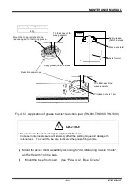
Fig. 5.5 Removing cover (TSL3000)
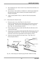
5) Remove the DC cable (blue and red), the SVIF cable (blue) and the encoder
cable (blue) connected to the X8YC (main board) as well as the hand I/O cable
(blue) and the brake cable (blue) connected to the X8YX (I/O board).
6)
Remove the cables (red x 1 line, blue x 1 line, black x 2 lines) connected to the
PS1 and the PS2.
(See Fig. 4.10.)
When removing the
interior panel unit, be
sure to remove the key.
Countersunk screws
(M3 x 6 x 8 pcs.)
ACIN connector