


MAINTENANCE MANUAL
169
STE 85357
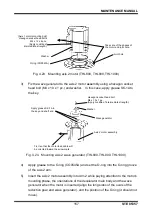
11) Connect the connector and set the zero points of Axes 3 and 4. After that,
while pressing the brake release switch, manually move the ball screw in the
vertical direction. Check if you feel a catch in the movement or if the
movement of the ball screw is less smooth. If such a problem has been found,
the ball screw center may be misaligned. Go back to where the center can be
aligned, and go through the work procedure again.
12) If there is no problem, put cables back to where there were and mount the axis
2 arm cover. Replacement of the timing belt has been completed.
13) Carry out a test operation of Axes 3 and 4 and make sure that each part
operates properly.
4.5.4
Replacing Axis 4 Timing Belt
!
CAUTION
• When the axis 4 timing belt is replaced with a new one, the axis 3 should be disassembled
also due to the structure. Therefore, strictly observe the cautions on replacement of the
axis 3 timing belt and motor also.
• When the ball screw nut integrated with the ball screw spline shaft is disconnected, take
utmost care not to cause the ball screw spline shaft to come off. Otherwise, the ball in the
ball screw nut will drop and the ball screw nut integrated with the ball screw spline shaft
cannot function any further.
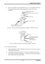
1)
Remove the arm 2 cover, the axis 3 motor assembly, the axis 3 timing belt, the
ball screw nut and the ball screw spline shaft.
For the disconnecting procedures, see Steps 1) through 5) of
“Para. 4.5.3,
Replacing Axis 3 Timing Belt.”
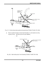
2)
Loosen two (2) tension adjustment bolts (M4 x 16) for the axis 4, remove four
(4) flange head bolts (M4 x 10) securing the axis 4 motor plate, and then pull out
the axis 4 motor assembly. Pull out the axis 4 timing belt upward.