MAINTENANCE MANUAL
44
STE 85357
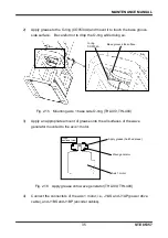
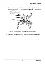
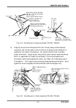
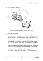
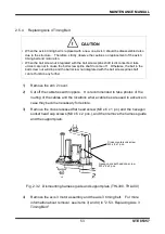
Fig. 2.24 Mounting axis 3 pulley and plate (THL300, THL400)
3)
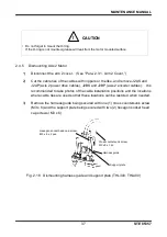
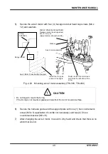
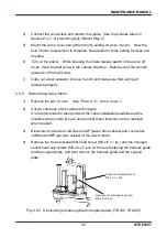
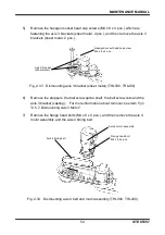
Hang the axis 3 motor timing belt to the arm 3 motor pulley, and temporarily
secure the axis 3 motor plate to Arm 2 with four (4) flange head bolts (M4 x 8,
application of Loctite not necessary). Be careful with the motor mounting
phase at this time. Apply tension using two (2) axis 3 tension adjustment bolts
(M3 x 12, application of Loctite not necessary). (For the belt replacement
procedures and tension adjustment values, see
“Para. 2.6.3, Replacing Axis 3
Timing Belt.”) Then, tighten the temporarily tightened flange head bolts. Next,
tighten the tension adjustment bolts and fasten with the hexagon nuts.
Fig. 2.25 Mounting axis 3 motor assembly (THL300, THL400)
[Axis 2 drive motor set bolt]
Hexagon socket head cap screw
M3 x 10 x 4 pcs.
(Apply medium strength Loctite.)
Set
screws
4 x 5 x 2 pcs.
Set
screws
3 x 5 x 2 pcs.
Axis
Set
screw
holes
Cross section B-B
B
B
D cuts
(Flat plane of motor
axis)
(
Apply
medium strength Loctite.)
Axis 3 motor
Axis 3 motor plate
Pulley
Be sure to secure the tension
adjustment bolt so that it faces
the direction of the arrow.
Fasten so that the motor
lead wire faces the
direction of the arrow.
Washer
[Axis 3 motor plate set
bolt]
Flange head bolt
M4 x 8 x 4 pcs.
[
Bolts for adjusting axis 3 tension
]
M3 x 12 x 2 pcs.
Hexagon nuts
Axis 3 motor
assembly
Fasten so that the
motor lead wire faces
the direction of the
arrow.

