


MAINTENANCE MANUAL
42
STE 85357
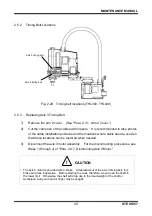
2.4.7
Dismounting Axis 3 Motor
!
CAUTION
• The axis 3 motor is provided with a brake. At replacement of the axis 3 motor, this brake
becomes inoperative. Before starting the work, therefore, move down the ball screw spline
to the lower limit. Otherwise, the shaft will drop due to the dead weight of the shaft or
workpiece, and your hand or finger may be caught.
1)
Remove t
he arm 2 cover. (See “Para. 2.3.1, Arm 2 Cover.”)
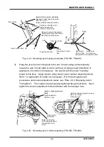
2)
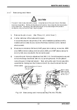
Cut the cable ties of the cables with nippers.
It is recommended to take photos of the cable installation positions and the
locations where cable ties are used so that these locations can be restored
when needed.
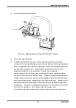
3)
Disconnect connectors J3AS and J3AP (power drive cables), connectors J3BS
and J3BP (encoder cables) and connectors J3DS and J3DP (brake cables) for
Axis 3, which are connected to the connector panel.
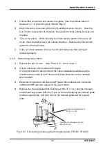
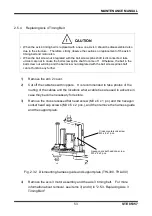
4)
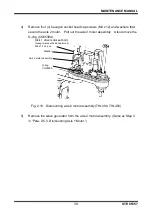
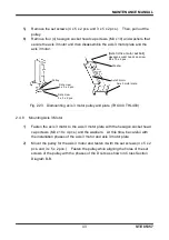
Loosen the axis 3 tension adjustment bolt (M3 x 12 x 2 and hexagonal nuts) and
remove the flange head bolts (M4 x 8 x 4) securing the axis 3 motor plate to
cancel the axis 3 timing belt tension. Next, pull out the axis 3 motor assembly
upward while making sure that it does not touch the sheet metal and the ball
screw spline.
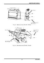
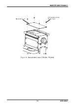
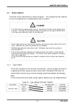
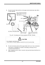
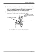
Fig. 2.22 Dismounting axis 3 motor assembly (THL300, THL400)
Bolts for adjusting axis 3 tension
M3 x 12 x 2 pcs.
Hexagon nuts
[Axis 3 motor
plate set bolt]
Flange head bolt
M4 x 8 x 4 pcs.
Axis 3 motor
assembly
Axis 3 motor
assembly