MAINTENANCE MANUAL
43
STE 85357
5)
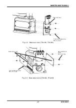
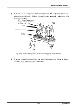
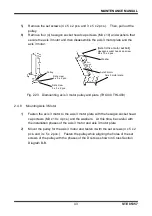
Remove the set screws (4 x 5 x 2 pcs. and 3 x 5 x 2 pcs.). Then, pull out the
pulley.
6)
Remove four (4) hexagon socket head cap screws (M3 x 10) and washers that
secure the axis 3 motor and then disassemble the axis 3 motor plate and the
axis 3 motor.
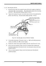
Fig. 2.23 Dismounting axis 3 motor pulley and plate (THL300, THL400)
2.4.8
Mounting Axis 3 Motor
1)
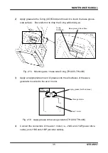
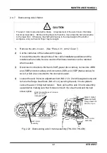
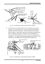
Fasten the axis 3 motor to the axis 3 motor plate with the hexagon socket head
cap screws (M3 x 10 x 4 pcs.) and the washers. At this time, be careful with
the installation phases of the axis 3 motor and axis 3 motor plate.
2)
Mount the pulley for the axis 3 motor and fasten it with the set screws (4 x 5 x 2
pcs. and 3 x 5 x 2 pcs.). Fasten the pulley while aligning the holes of the set
screws of the pulley with the phases of the D cuts as shown in Cross Section
Diagram B-B.
Set screw
4 x 5 x 2 pcs.
Pulley
[Axis 3 drive motor set bolt]
Hexagon socket head cap screw
M3 x 10 x 4 pcs.
Washer
Axis 3 motor plate
Axis 3 motor
Set screw
3 x 5 x 2 pcs.

