


MAINTENANCE MANUAL
121
STE 85357
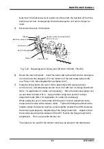
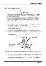
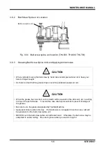
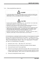
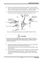
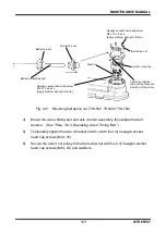
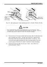
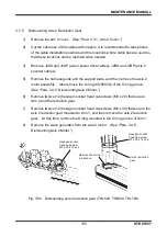
Fig. 3.39 Dismounting ball screw spline nut (THL500, THL600, THL700)
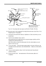
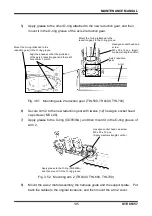
10)
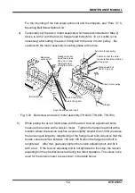
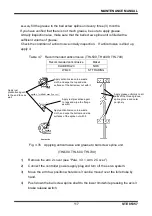
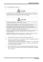
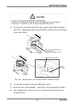
Insert the disconnected ball spline nut into the ball screw spline shaft.
A marking for phase adjustment is stamped on both the ball screw spline shaft
and the ball spline nut. Align the two markings when inserting the ball spline
nut. To prevent the nut from slipping off, wind cable ties around near the top
and bottom of the shaft.
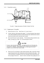
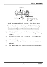
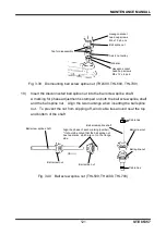
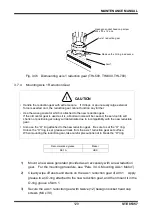
Fig. 3.40 Ball screw spline nut (THL500, THL600, THL700)
Hexagon socket
head cap screws
M4 x 12 x 6 pcs.
Washer
Hexagon socket
head cap screws
M5 x 12 x 6 pcs.
Tap for disassembly
Ball spline nut
Axis 4 nut pulley
Cable ties
Cable ties
Ball screw spline shaft
Ball screw nut
Ball spline nut
Ball screw spline shaft
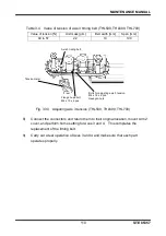
Align the phase of each marking(number).
* It should be noted that the ball spline nut
has two marks, which are not on the flange
side.
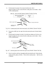
Ball screw nut
Ball spline nut