


MAINTENANCE MANUAL
191
STE 85357
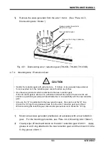
7)
After changing the axis 1 motor, move Arm 1 by hand and check that there is no
abnormal sound.
8)
Set up the axis 1 home position to complete axis 1 reduction gear replacement.
Because the reduction gear is changed, home position settings of Axes 2
through 4 are required.
9)
Carry out a test operation of Axis 1 to make sure that each part operates
properly.
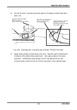
4.7.5
Dismounting Axis 2 Reduction Gear
1)
Remove the arm 2 cover. (See
“Para. 4.3.1, Arm 2 Cover.”)
Remove the harness guide and the support plate, and then remove the axis 2
motor assembly. Also remove the O-ring (CO0545A) of the O-ring groove.
(See
“Para. 4.4.5, Dismounting Axis 2 Motor.”)
2)
Remove sixteen (16) hexagon socket head bolts (M4 x 20) that secure Arm 2
and the reduction gear.
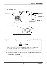
3)
Remove twelve (12) hexagon socket head bolts (M4 x 30) that secure the axis 2
reduction gear mounted to Arm 1, and then remove the axis 2 reduction gear.
At this time, remove the O-ring mounted in the O-ring groove of Arm 1.
4)
Remove the wave generator from the axis 2 motor. (See
“Para. 4.4.5,
Dismounting Axis 2 Motor.”)
Fig. 4.54 Dismounting axis 2 reduction gear (THL800, THL900, THL1000)
Hexagon socket head bolts
M4 x 20 x 16 pcs.
Hexagon socket
head bolts
M4 x 30 x 12 pcs.
Axis 2 reduction
gear
Remove the O-ring
in advance.