ISDN Interfaces
Strata CT I&M Manual October 2000
10-17
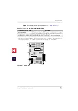
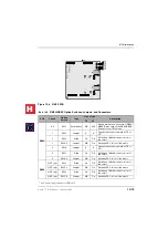
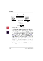
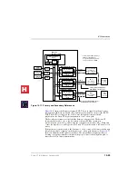
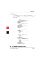
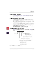
Figure 10-10 RBSU/RBSS Location of LEDs and Connector Locations
RBSU/RBSS BRI Cable Jacks and Connectors
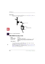
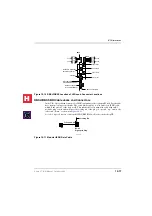
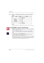
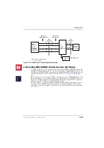
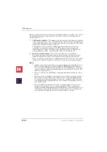
In the U.K., the standard connector for ISDN equipment is the eight-pin RJ jack. Patch cables
have eight-pole plugs at both ends. The same pinout applies to both ends of an ISDN cable,
which is the practice of the data world. This means that a flat untwisted cable with an RJ
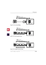
modular plug at both ends will have the locking tab of the plug on one end, “up;” and on the
other end, “down,” as shown in
A cord of up to 10 meters connects the ISDN BRI RJ45 wall jack to the desktop TE.
Figure 10-11 Modular ISDN Data Cable
RBSU
Reset Switch
(resets RBSU Firmware)
RS232C Connector
for Call-Data Monitor
RJ45 8-pin (shielded)
Modular Connector
BSY
TS
LOS
FS
BSY
TS
LOS
FS
2795
RBSS
3rd Circuit
2nd Circuit
1st Circuit
4th Circuit
BSY
TS
LOS
FS
BSY
TS
LOS
FS
CCT2
CCT1
CCT4
CCT3
TB3 (FG)
TB1 and TB2 (PFT)
3039 CT I&M
Four-pair wire
Locking Tab
RJ-45
Eight-pole Plug
H
C
Summary of Contents for Strata CT
Page 36: ...Strata CT Configuration 1 22 Strata CT I M Manual October 2000 H C ...
Page 94: ...Strata CT Installation 2 58 Strata CT I M Manual October 2000 H C ...
Page 242: ...Peripheral Installation 6 54 Strata CT I M Manual October 2000 H C ...
Page 258: ...ACD Installation 7 16 Strata CT I M Manual October 2000 H C ...
Page 274: ...Fault Finding 8 16 Strata CT I M Manual October 2000 H C ...
Page 364: ...ISDN Interfaces 10 38 Strata CT I M Manual October 2000 H C ...
Page 370: ...Notes to Users A 6 Strata CT I M Manual October 2000 H C ...


