Fault Finding
Strata CT I&M Manual October 2000
8-7
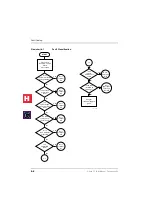
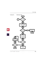
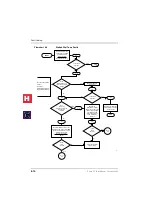
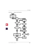
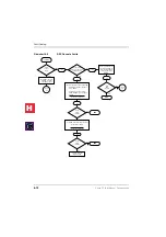
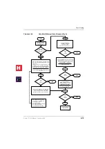
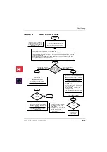
Fault Isolation Flowcharts
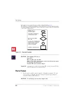
The following troubleshooting flowcharts are available to aid in fault isolation. Toshiba
recommends reading the previous text in this chapter before proceeding to
to begin fault isolation.
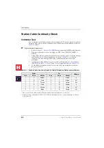
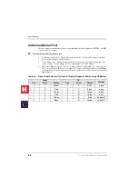
Table 8-4
Station Cable Continuity Check for Electronic Telephone Cables using
Ohmmeter
From
To
Voltage
Pair
Wire
Colour
Pair
Wire
Colour
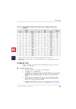
1
T
Green
1
1.
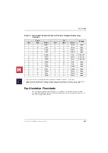
The green-red, black-yellow and white-blue measurements should be within 10% of each other.
2
T
Black
open
1
R
Red
2
T
Black
open
1
T
Green
2
R
Yellow
open
1
R
Red
2
R
Yellow
open
1
T
Green
1
R
Red
40 ohms
2
2.
This is the maximum allowable reading for all digital and electronic telephone cable runs except if connecting an
HDSS console to circuits 7 and 8 of a PEKU, then the maximum cable restriction is 20 ohms, not 40 ohms.
2
T
Black
2
R
Yellow
40 ohms
2
3
T
White
3
R
Blue
40 ohms
2
3
T
White
1
R
Red
open
3
R
Blue
1
R
Red
open
3
T
White
1
T
Green
open
3
R
Blue
1
T
Green
open
3
T
White
2
T
Black
open
3
R
Blue
2
T
Black
open
3
T
White
2
R
Yellow
open
H
C
Summary of Contents for Strata CT
Page 36: ...Strata CT Configuration 1 22 Strata CT I M Manual October 2000 H C ...
Page 94: ...Strata CT Installation 2 58 Strata CT I M Manual October 2000 H C ...
Page 242: ...Peripheral Installation 6 54 Strata CT I M Manual October 2000 H C ...
Page 258: ...ACD Installation 7 16 Strata CT I M Manual October 2000 H C ...
Page 274: ...Fault Finding 8 16 Strata CT I M Manual October 2000 H C ...
Page 364: ...ISDN Interfaces 10 38 Strata CT I M Manual October 2000 H C ...
Page 370: ...Notes to Users A 6 Strata CT I M Manual October 2000 H C ...

