111
18
Trial Operation
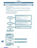
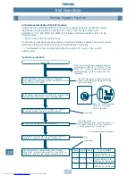
Procedure and Summary of Trial Operation
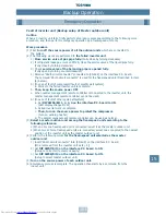
Outline of procedure
For a trial operation, follow the procedure below.
* Ensure you write the check results of trial operation in the check lists 1 and 2. It will be an
important document for servicing or maintenance in the future.
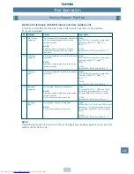
Check before trial operation
Prior to the trial operation, confirm whether there is a fault with the installation work using
“Check list 1”.
CHECK LIST 1
Check additional amount of refrigerant.
CHECK LIST 2
• Calculate the additional amount of refrigerant from the pipe dia. at liquid side and length of
pipe to be connected. Write the total length of the liquid side pipes for each dia. in the
following table, and calculate the additional amount of refrigerant. (The refrigerant amount
charged in the outdoor unit is only for the outdoor unit, and refrigerant for piping is not
included.)
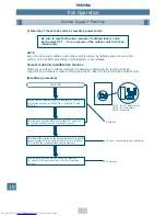
Check before trial operation
Implementation of trial operation check
End
(In case of abnormal operation in
trial operation)
Clear the error
Check the basic items, especially installation
work. Ensure you write the check results in the
check lists 1 and 2.
]
[
Refer to Troubleshooting to clear the error,
and then implement the trial operation again.
Implement check in sequence according to
each flowchart of trial operation procedure.
]
[
]
[
Is the capacity of field fuse adequate
?
Outdoor unit
A
Indoor unit
A
Is the dia. of power source cable correct
?
Outdoor unit
mm
2
Indoor unit
mm
2
Is the control transmission line correct
?
(Indoor/Outdoor connecting terminal: PQ, Type: Shield wire) Cable dia.
mm
2
Is the power of indoor units collectively supplied
?
Is the earth grounded
?
Is the insulation good
?
(10M
Ω
or more)
M
Ω
or more
Is the voltage good
?
(Within 380/400/415V±10%)
V for outdoor unit
Is the connecting cable dia. correct
Is the branching kit correct
?
Is the drain water flow sufficient
?
(Indoor unit)
Is the heat insulation of cables good
?
(Connecting cables, branching kits)
Is there no short-circuit of discharge air of indoor/outdoor units
?
Are vacuuming and addition of refrigerant performed after airtight test of cables
?
Are the valves fully opened
?
Gas side
Liquid side
Balance side
Pipe dia. at liquid side Standard refrigerant amount (kg/m) Total length of liquid side pipes (m)
Additional refrigerant amount for each liquid pipe
Ø6.4
0.030
X
=
kg
Ø9.5
0.065
X
=
kg
Ø12.7
0.115
X
=
kg
Ø15.9
0.190
X
=
kg
Ø19.0
0.290
X
=
kg
Ø22.2
0.420
X
=
kg
Additional refrigerant amount
kg
Summary of Contents for MM-A0160HX
Page 1: ...Service Manual Air Conditioner Multi Split Type System Modular Multi System HFCR407C A90 0130 ...
Page 2: ......
Page 133: ...134 20 Additional Literature and Contacts ...
Page 134: ...135 20 Additional Literature and Contacts ...
Page 135: ...TOSHIBA AIR CONDITIONING www toshiba aircon co uk MADE IN UK A90 0130 Revised April 2001 ...


