72
14
Troubleshooting
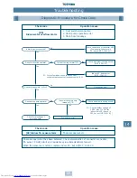
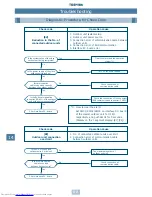
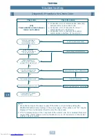
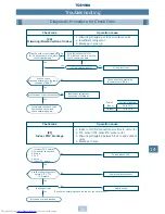
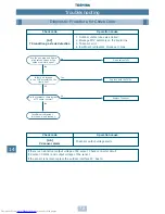
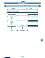
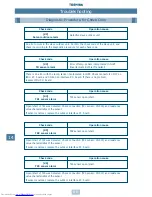
Diagnostic Procedure for Check Code
Check code
Operation cause
1. Connection error of communication cable (PQ)
between indoor and outdoor units
2. Connection error of (XY) for outdoor units
[97]
3. Power source system error of the central controller
BUS communication alarm (1)
and indoor unit
4. Noise of peripheral devices
5. Power failure
6. Indoor P.C. board error, central controller error
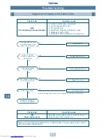
Are X,Y and PQ
communication cables normal
?
Is the operation status
of the indoor unit reflected on
the central controller
?
Is connection of CN101 on
the indoor P.C. board normal
?
(When indoor PQ communication
cable is connected.)
Is there a connection error
of power source wiring
?
Is the source power
of either central controller or
indoor/outdoor turned on
?
Clear the alarm after turning
on the power source, and
start the operation.
Check communication cable.
Check power source wiring.
Check connector connection.
Check connector connection.
Clear the alarm after turning
on the power source, and
start the operation.
Central controller error
Eliminate noise interference.
Indoor P.C. board error
No
Yes
No
Yes
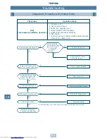
Is connection of CN602
on interface P.C. board
of the master outdoor
unit normal
?
No
Yes
Yes
No
No
Yes
Is the network address
different from main or sub
remote controller
?
No
Yes
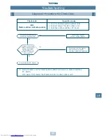
Did power failure occur
?
Yes
No
Is [97] displayed only
on the central controller
?
No
Yes
No
Yes
Is there noise interference, etc.
?
Is there noise interference, etc.
?
Yes
No
Yes
No
Summary of Contents for MM-A0160HX
Page 1: ...Service Manual Air Conditioner Multi Split Type System Modular Multi System HFCR407C A90 0130 ...
Page 2: ......
Page 133: ...134 20 Additional Literature and Contacts ...
Page 134: ...135 20 Additional Literature and Contacts ...
Page 135: ...TOSHIBA AIR CONDITIONING www toshiba aircon co uk MADE IN UK A90 0130 Revised April 2001 ...


