22
7
Wiring Diagrams
Indoor Units
L
N
RED
WHI
1
1
3
3
ORN
2
2
5
5
6
6
BLU
YEL
RED
YEL
BLU
ORN
BLK
CN03
CN07
CN25
CN51
55
33
11
22
44
66
CN27
CN50
CN16
BLK
BLU
ORN
RED
WHI
RED
WHI
BLK
CN26
55
33
11
22
44
66
WHI
BLU
BLU
BLU
55
33
11
22
CN10
WHI
BLU
BLU
BLU
BLU
BLU
1
1
3
3
5
5
1
1
2
2
1
1
2
2
CN01
CN12
YEL
BLK
WHI
33
11
44
22
CN02
B
A
C
B
A
C
ORN
YEL
BLU
CN04
22
11
WHI
CN05
22
11
BLU
CN20
22
11
YEL
22
44
66
11
CN23
RED
GRN
WHI
BLK
1
1
2
2
31
31
1
1
2
2
CN101
CN25
CN08
CN09
CN1
1
1
1
2
2
3
3
4
4
5
5
6
6
WHI
YEL
ORN
BLU
BRN
RED
6
6
4
4
3
3
1
1
2
2
5
5
WHI
YEL
ORN
BLU
BRN
RED
BLK
Q
P
GR
Y
GR
Y
Q
P
4
4
RY
0
1
RY
0
2
RY
0
3
RY
0
4
33
11
FM
1
1
3
3
5
5
7
7
9
9
1
1
3
3
5
5
33
11
44
22
1
1
3
3
1
1
2
2
F
H
M
L
UL
MCC-1355-01
TR
CN28
22
TA
TC2
TC1
PS
MCC-1361-01
PMV
RED
2
2
RED
7
7
8
8
9
9
BRN
BLK
GRN/YEL
RC
WHI
GR
Y
1
1
3
3
ORN
2
2
5
5
6
6
BLU
YEL
ORN
RED
4
4
FM
1
1
3
3
5
5
7
7
9
9
RED
7
7
8
8
9
9
BRN
BLK
GRN/YEL
RC
WHI
GR
Y
2
2
4
4
6
6
8
8
BRN
BLK
YEL
BLK
ORN
BLU
YEL
RED
FC
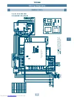
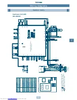
Built-In Duct
MM-B140, MM-B112, MM-B080, MM-B056
Symbol
Name
F
F
use (PCB)
FM
Fan Motor
PMV
Pulse Modulating V
alve
PS
P
ressure Sensor
RC
R
unning Capacitor
RY01~R
Y04
R
elay
TA
Temperature Sensor
TC
1
Temperature Sensor
TC
2
Tempterature Sensor
TR
Transformer
FC
Ferrite Core
Power Supply
220/240
~50Hz
Remote
Controller
(Optional)
Communication
Increase Fan Speed Option
Connector Assembly
(Accessory)
1.
The dashed line indicates wiring on the site.
2. and indicates terminal blocks and the
numbers within them are terminal numbers.
Summary of Contents for MM-A0160HX
Page 1: ...Service Manual Air Conditioner Multi Split Type System Modular Multi System HFCR407C A90 0130 ...
Page 2: ......
Page 133: ...134 20 Additional Literature and Contacts ...
Page 134: ...135 20 Additional Literature and Contacts ...
Page 135: ...TOSHIBA AIR CONDITIONING www toshiba aircon co uk MADE IN UK A90 0130 Revised April 2001 ...


