10
6
F
2
S
0
7
8
9
2.2 Protection Scheme
GRT100 provides the following protection schemes with measuring elements in parentheses.
Appendix A shows block diagrams of the GRT100 series.
Current differential protection (DIFT)
Restricted earth fault protection (1REF-3REF)
Time-overcurrent protection (1OC-3OC, 1OCI-3OCI, 1EF-3EF and 1EFI-3EFI)
Thermal overload protection (THR)
Frequency protection (FRQ)
Overexcitation protection (V/F)
Trip and/or indication of external devices (Buchholtz relay, pressure or temperature sensing
devices etc.)
The number of measuring elements for the restricted earth fault protection and time-overcurrent
protection is dependent on the relay models.
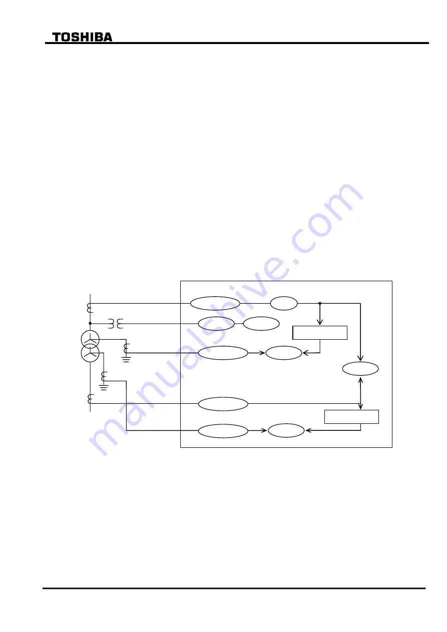
Figure 2.2.1 and 2.2.2 show the relationship between AC inputs and the measuring elements
applied in each model.
Figure 2.2.1 Measuring Elements of Model 100s
Calculate 3I
0
Calculate 3I
0
GRT100
1CT
1nCT
2nCT
VT
HV
LV
2CT
1OC/1OCI
THR
FRQ
V/F
1EF/1EFI
DIFT
2OC/2OCI
2EF/2EFI
1REF
2REF
Summary of Contents for GRT100 Series
Page 142: ... 141 6 F 2 S 0 7 8 9 Appendix A Block Diagram ...
Page 144: ... 143 6 F 2 S 0 7 8 9 Appendix B Signal List ...
Page 159: ... 158 6 F 2 S 0 7 8 9 ...
Page 160: ... 159 6 F 2 S 0 7 8 9 Appendix C Variable Timer List ...
Page 162: ... 161 6 F 2 S 0 7 8 9 Appendix D Binary Output Default Setting List ...
Page 165: ... 164 6 F 2 S 0 7 8 9 ...
Page 166: ... 165 6 F 2 S 0 7 8 9 Appendix E Details of Relay Menu and LCD and Button Operation ...
Page 174: ... 173 6 F 2 S 0 7 8 9 Appendix F Case Outline Flush Mount Type Rack Mount Type ...
Page 179: ... 178 6 F 2 S 0 7 8 9 ...
Page 180: ... 179 6 F 2 S 0 7 8 9 Appendix G External Connections ...
Page 185: ... 184 6 F 2 S 0 7 8 9 ...
Page 200: ... 199 6 F 2 S 0 7 8 9 ...
Page 201: ... 200 6 F 2 S 0 7 8 9 Appendix J Return Repair Form ...
Page 205: ... 204 6 F 2 S 0 7 8 9 Customer Name Company Name Address Telephone No Facsimile No Signature ...
Page 206: ... 205 6 F 2 S 0 7 8 9 ...
Page 207: ... 206 6 F 2 S 0 7 8 9 Appendix K Technical Data ...
Page 220: ... 219 6 F 2 S 0 7 8 9 ...
Page 221: ... 220 6 F 2 S 0 7 8 9 Appendix M Symbols Used in Scheme Logic ...
Page 224: ... 223 6 F 2 S 0 7 8 9 ...
Page 225: ... 224 6 F 2 S 0 7 8 9 Appendix N Implementation of Thermal Model to IEC60255 8 ...
Page 228: ... 227 6 F 2 S 0 7 8 9 ...
Page 229: ... 228 6 F 2 S 0 7 8 9 Appendix O IEC60870 5 103 Interoperability and Troubleshooting ...
Page 241: ... 240 6 F 2 S 0 7 8 9 Appendix P Modbus Interoperability ...
Page 255: ... 254 6 F 2 S 0 7 8 9 ...
Page 256: ... 255 6 F 2 S 0 7 8 9 Appendix Q Inverse Time Characteristics ...
Page 259: ... 258 6 F 2 S 0 7 8 9 ...
Page 260: ... 259 6 F 2 S 0 7 8 9 Appendix R Failed Module Tracing and Replacement ...
Page 266: ... 265 6 F 2 S 0 7 8 9 Appendix S Ordering ...
Page 269: ... 268 6 F 2 S 0 7 8 9 3 1 Oct 2 2017 Republished under spin off company ...
Page 270: ......


