December 2000 © TOSHIBA TEC
2 - 37
DP4500/3500 ADJUSTMENT
2.8 Adjustment of Angle of the Printed Image
(1) Print out a grid pattern in the test print mode (04-142). Measure the deviation A (see the figure below)
against the distance of 240mm in the feeding direction on the grid pattern.
(2) Remove the rear side upper cover.
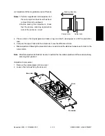
(3) Look at the scale on the frame and write down the position of the stay before making an adjustment.
(4) Loosen the adjustment screw and slide the stay as much as the deviation A on the printed grid pattern
in the direction as described below to adjust the deviation of the laser optical unit.
ex.) If the grid line is slanted by 1mm to the rear side, slide the stay 1mm downward.
240
A
240
A
Feeding
direction
Feeding
direction
(a) The grid line is slanted to the rear
side against the feeding direction.
n
Slide the stay downward.
(b) The grid line is slanted to the front
side against the feeding direction.
n
Slide the stay upward.
Stay
Adjustment screw
Stay
Scale
(space between
each mark: 1mm)
Note: Print out an image and check if it is positioned properly. Adjust the printer section following “2.3
Dimentional Adjustment of Copied Image” if necessary.
Summary of Contents for DP3500
Page 91: ...DP4500 3500 PREVENTIVE MAINTENANCE 3 12 December 2000 TOSHIBA TEC ...
Page 95: ...DP4500 3500 SUPPLIES 4 4 December 2000 TOSHIBA TEC ...
Page 213: ...DP4500 3500 TROUBLESHOOTING 5 118 December 2000 TOSHIBA TEC ...
Page 253: ...DP4500 3500 UPDATING THE FIRMWARE 6 40 December 2000 TOSHIBA TEC ...
Page 256: ...DP4500 3500 WIRE HARNESS CONNECTION DIAGRAMS 7 4 December 2000 TOSHIBA TEC ...


